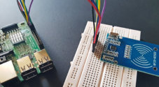
In this Raspberry Pi RFID attendance system project, we will be showing you how to set up and program your very own attendance system that makes use of the RC522 RFID reader.
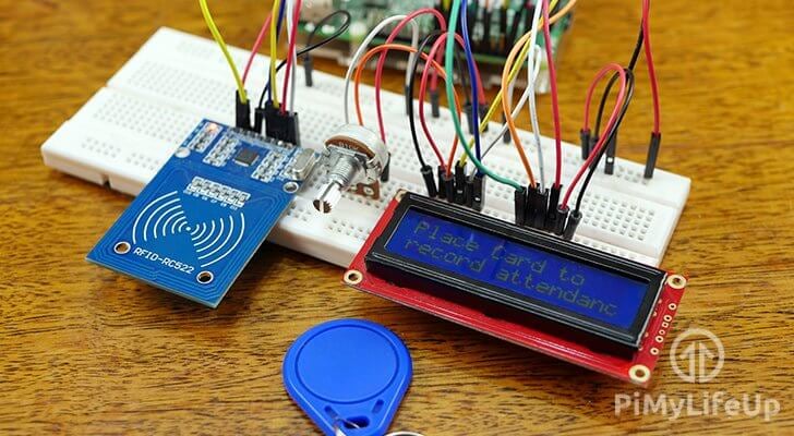
Throughout this project, we will be showing you will learn how to put together a circuit that makes use of both the RFID RC522 reader and a 16×2 LCD.
We start by showing you all the steps required to connect these circuits to the Raspberry Pi’s GPIO pins. We will also show you how to test each circuit so that it is working as it should. This helps ensure everything will be ready to be utilized in our RFID attendance system.
In the second part of the tutorial, we will walk you through all the steps to setting up a database. We will also be writing Python scripts that will talk to the database to mark attendance for individual RFID cards.
Finally, we get you to set up a straightforward PHP script that allows you to see the data produced by the RFID attendance system visually.
There is quite a bit to do in this tutorial but you will be quite happy once you have a working attendance system.
You Might Also Like


Equipment
You will need the following pieces of equipment to be able to complete this project.
Recommended
- Raspberry Pi Amazon
- Micro SD Card Amazon
- Power Supply Amazon
- Ethernet Cable Amazon or Wi-Fi Amazon
- RC522 RFID Reader Amazon
- 16×2 LCD Amazon with header pins Amazon
- 10k Ohm Potentiometer Amazon
- Breadboard Amazon
- Breadboard Wire Amazon
Optional
Video
We have put together a video that will go through all the steps to set up this RFID attendance system. It’s quite long but covers all the steps.
If you like a more thorough explanation, then I highly recommend reading through the full written tutorial underneath the video. We have put a lot of work into it and hope that you like it.
Preparing Raspbian for your RFID Attendance System
1. To start, we will first ensure that everything is up to date on our Raspbian installation by running the following two commands on the Raspberry Pi.
sudo apt update
sudo apt upgradeCopy
2. We will now install all the packages that we will be relying on for the next few sections.
Let’s begin by installing build-essential, git,python3-dev, python3-pip, and python3-smbus by running the command below.
sudo apt install build-essential git python3-dev python3-pip python3-smbusCopyBuilding the 16×2 LCD Display Circuit
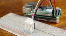
1. To start our tutorial, we will first begin setting up the 16×2 LCD. We will be quickly running through the process of setting this all up. If you want to learn more you can check out our tutorial on the 16×2 LCD Display.
For this section of the tutorial make sure that you have the following ready to go.
- 8 pieces of Male to Male Breadboard Wire
- 8 pieces of Male to Female Breadboard Wire
- 16×2 LCD Display
- 10k Ohm Potentiometer
- Breadboard
2. Once you have all the parts required, you can start assembling the circuit by observing the diagrams and steps below.
Connecting the LCD to your Raspberry Pi is a pretty simple process if you follow our guide. We have included the physical pin number for each connection that you need to make.
To begin with, let’s connect up our various components with the breadboard.
- 5V (Physical Pin 2) to breadboard positive rail
- Ground (Physical Pin 6) to breadboard ground rail
- Place the 16×2 LCD Display into the right side of the breadboard
- Place the potentiometer into the left side of the breadboard next to the LCD Display.
- Connect the left pin of the potentiometer to the ground rail
- Connect the right pin of the potentiometer to the positive rail
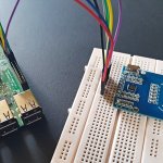
3. Now begin connecting the LCD display to your Raspberry Pi.
- Pin 1 of LCD (Ground) to breadboard ground rail
- Pin 2 of LCD (VCC / 5V) to breadboard positive rail
- Pin 3 of LCD (V0) to middle wire of the potentiometer
- Pin 4 of LCD (RS) to GPIO4 (Physical Pin 7)
- Pin 5 of LCD (RW) to breadboard ground rail
- Pin 6 of LCD (EN) to GPIO24 (Physical Pin 18)
- Pin 11 of LCD (D4) to GPIO23 (Physical Pin 16)
- Pin 12 of LCD (D5) to GPIO17 (Physical Pin 11)
- Pin 13 of LCD (D6) to GPIO18 (Physical Pin 12)
- Pin 14 of LCD (D7) to GPIO22 (Physical Pin 15)
- Pin 15 of LCD (LED +) to breadboard positive rail
- Pin 16 of LCD (LED -) to breadboard ground rail
RFID Attendance System LCD Wiring Diagram

Testing the 16×2 LCD Display
1. Now that the circuit has been set up let’s go ahead and test it to ensure that everything was wired correctly.
To start, go ahead and clone the Adafruit CharLCD library that we will be utilizing for this project. If your display board uses the HD44780 controller, then it will work with no issues.
To clone the library to your Raspberry Pi run the following command on it.
git clone https://github.com/pimylifeup/Adafruit_Python_CharLCD.gitCopy2. Now with the library cloned to our Raspberry Pi, we need to run the setup script. This script will install the library so that any Python scripts can utilize it.
Run the following two commands to move into the newly cloned directory and run the setup.py script.
cd ./Adafruit_Python_CharLCD
sudo python3 setup.py installCopy
3. With the library installed to the Raspberry Pi, we need to go ahead and edit an example file. We need to do this to test the circuit as we are using different pins to what the example utilizes.
Begin editing the file by running the following command.
nano ~/Adafruit_Python_CharLCD/examples/char_lcd.pyCopy4. In this file, find the “# Raspberry Pi pin configuration:” section and change it so that the values match what we have below.
# Raspberry Pi pin configuration:
lcd_rs        = 4
lcd_en        = 24
lcd_d4        = 23
lcd_d5        = 17
lcd_d6        = 18
lcd_d7        = 22
Once the changes are made, save the file by pressing CTRL + X then Y and then ENTER.
5. Now before we go ahead and run our new modified example we will need to install the Raspberry Pi’s GPIO Python library.
To install the required library run the following command.
sudo pip3 install RPi.GPIOCopy6. To test that everything is working lets now run that python script by running the command below. If everything is working as it should, you should now see text displayed across your LCD.
python3 ~/Adafruit_Python_CharLCD/examples/char_lcd.pyCopyBuilding the RFID RC522 Reader Circuit
1. Now that you have set up the 16×2 LCD Display we will now move onto adding the RFID reader into this circuit.
For this section on wiring the RFID RC522 to the circuit, you will require the following pieces of equipment ready.
- 1 piece of Male to Male Breadboard Wire
- 6 pieces of Male to Female Breadboard Wire
- RFID RC522 Read/Writer
- Breadboard
2. Once you have everything that you need for the RFID circuit we can then proceed on to wiring everything up, this will be slightly more complicated thanks to the LCD circuit being already set up.
Please note that this circuit diagram is assuming that you have followed the steps in the previous section for the LCD Display. If you are not utilizing the LCD, make sure you connect Physical Pin 6 on the Raspberry Pi to the ground rail on the breadboard.
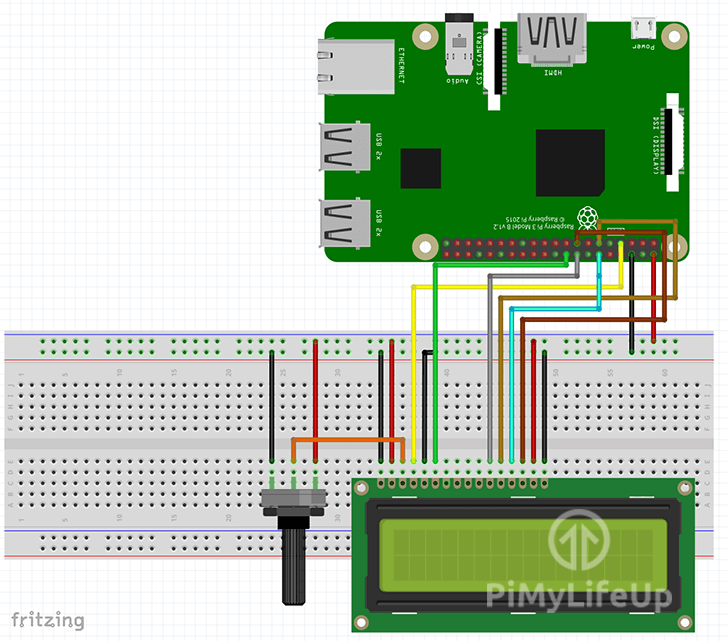
Follow the diagrams and steps below to wire the RFID circuit up to the Raspberry Pi.
- SDA connects to GPIO8 (Physical Pin 24)
- SCK connects to GPIO11 (Physical Pin 23)
- MOSI connects to GPIO10 (Physical Pin 19)
- MISO connects to GPIO9 (Physical Pin 21)
- GND connects to Breadboard Ground Rail.
- RST connects to GPIO25 (Physical Pin 22)
- 3.3v connects to 3v3 (Physical Pin 1)
RC522 RFID Attendance System Wiring Diagrams

Enabling the SPI interface
1. With the RFID now wired to our Raspberry Pi, we will need to go into the raspi-config tool to enable the SPI interface. This interface is required so that we can communicate with the RC522 module.
To do this, you need to first launch the raspi-config tool by running the following command.
sudo raspi-configCopy2. Upon running the command, you will see with a screen showing various options that you can configure.
For now, we are only interested in activating the SPI interface. If you want to learn more, you can check out our ultimate guide to the Raspi-Config tool.
On this screen use your ARROW keys to go down and select “5 Interfacing Options” and press ENTER.
3. On the next screen, you will want to use your ARROW keys to select the “P4 SPI” option, once selected press ENTER.
4. You will now need to confirm if you want to enable the SPI Interface. To this, you will want to use your ARROW keys to select “Yes” and then press ENTER once it’s selected.
5. The SPI Interface should now be successfully enabled, and you should now see the text “The SPI interface is enabled” appear on the screen.
Now before the SPI interface is fully enabled, we will need to restart the Raspberry Pi. We can achieve this by going back to the terminal by pressing ENTER and then ESC.
Enter the following command to restart the Raspberry Pi.
sudo rebootCopy6. Once the Raspberry Pi has finished rebooting, you can verify that the SPI interface has been enabled by running the following command.
This command will retrieve the list of enabled kernel modules and grab anything from that list that contains the text “spi“.
lsmod | grep spiCopyIf you see the text “spi_bcm2835” appear in the command line, then you are now ready to proceed to test that the circuit is working correctly. Once that is done we can set up our RFID powered attendance system.
If it doesn’t appear, then we recommend you check out our guide on setting up the RFID RC522 for other methods of enabling the correct kernel module.
Testing the RFID RC522
1. Let’s now install the spidev library to our Raspberry Pi by using the following “pip” command.
We rely on the spidev library to interact with the RFID reader interface.
sudo pip3 install spidevCopy2. Now that we have installed the spidev library to our Raspberry Pi we need to proceed to download the MFRC522 library by using the “pip” command.
This library is what will handle the grunt work for our RFID attendance system.
sudo pip3 install mfrc522Copy3. Now that we have both the MFRC522 library and the spidev library installed to our Raspberry Pi let’s go ahead and make a directory to keep our test script.
mkdir ~/pi-rfidCopy4. Now we will need to write a short script to test that our RC522 is, in fact, able to read RFID cards and that everything is wired correctly.
First, let’s open up our new script by running the following command, this will create a file called “read.py” in our recently created directory.
nano ~/pi-rfid/read.pyCopy5. Enter the following lines of code into this file. If you want an explanation of everything here, then we recommend checking out our full guide on the RFID RC522.
#!/usr/bin/env python

import RPi.GPIO as GPIO
from mfrc522 import SimpleMFRC522

reader = SimpleMFRC522()
try:
        id, text = reader.read()
        print(id)
        print(text)
finally:
        GPIO.cleanup()Copy
Once done, save the file by pressing CTRL + X then Y and ENTER.
6. Now test the RFID RC522 by running the following script and tapping your RFID chip on the reader.
python3 ~/pi-rfid/read.pyCopyThe Full Raspberry Pi RFID Attendance System Circuit
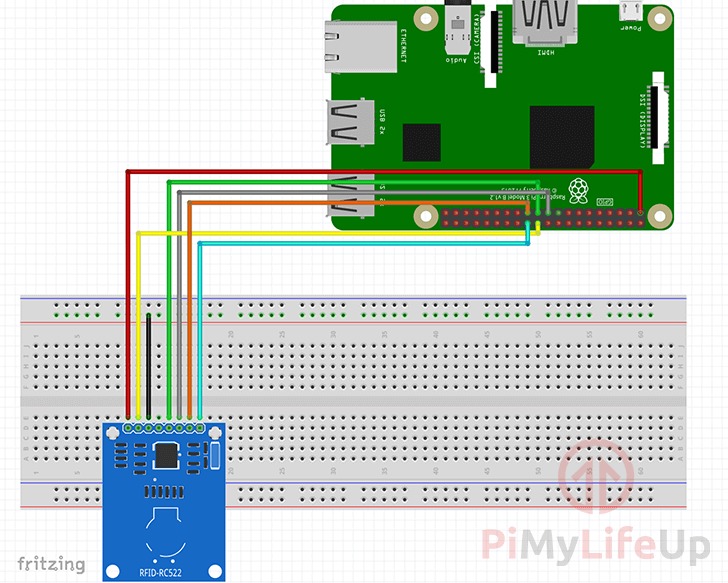
1. With both circuits now setup, double check that everything is working correctly. Test by running the test scripts that we quickly put together in a previous couple of sections.
If you are having issues, you can compare your final circuit to the diagrams below. These diagrams are designed to give you an idea of how the final circuit should look.
RFID Attendance System Circuit Schematic
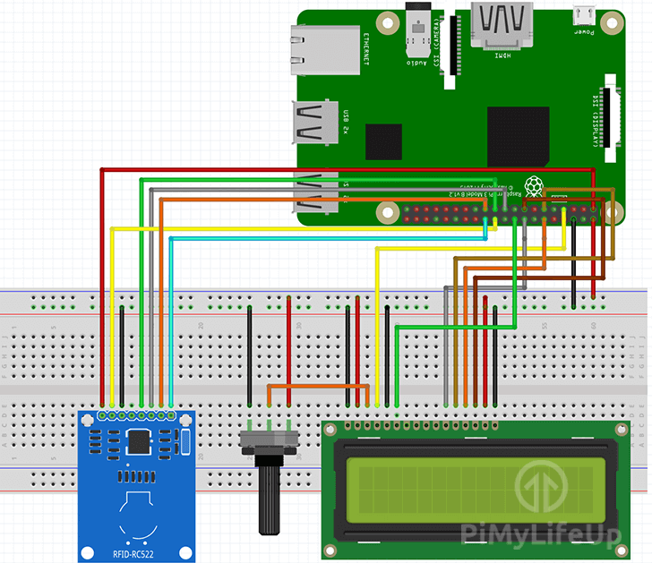
RFID Attendance System GPIO Pins Utilized

Preparing the RFID Attendance System Database
1. Now before we go ahead and program our RFID attendance system, we must first prepare and set up the MYSQL database. This database is where we will be keeping track of each RFID cards attendance and who owns that RFID card.
You can delve into setting up MYSQL a bit deeper by following our MySQL tutorial and PHPMyAdmin guide. Our RFID Attendance system will walk you through most of the basics but the extra guide will teach you how to setup useful tools like PHPMyAdmin.
Begin by installing MYSQL to your Raspberry Pi by running the following command on your Pi.
sudo apt-get install mysql-server -yCopy2. Next, we will need to run the “secure installation” script that comes packaged with MYSQL. This script will run you through some processes on making your MYSQL server more secure.
Run this script by running the following command within the terminal on the Raspberry Pi.
sudo mysql_secure_installationCopyWhen prompted make sure that you set a new password for the root MYSQL server. Additionally, you should answer “y” to most prompts such as disabling root login access to your MYSQL server.
3. Now let’s load up into the MYSQL command-line tool by running the following command. You will be prompted to enter the password you set in the previous step.
As MariaDB when installed utilizes “UNIX_SOCKET” as the authentication method by default, we are required to log in using the superuser, do this by using “sudo“.
sudo mysql -u root -pCopy4. Let’s begin by creating a database where we will be storing all of the data that we will be utilizing for our RFID attendance system.
We will be naming this database, “attendancesystem“. To create this database, run the following command.
CREATE DATABASE attendancesystem;Copy5. With our database created, let’s now create a user called “attendanceadmin” we will utilize this user in our Python scripts to read from our newly created database.
Make sure you set the password for this to something unique and hard to guess. For our example, we will be just using “pimylifeup” as the password.
CREATE USER 'attendanceadmin'@'localhost' IDENTIFIED BY 'pimylifeup';Copy6. Now that we have created our user we need to give it the rights to access our “attendancesystem” database.
We can do this by running the following command. This command will give our “attendanceadmin” user full privileges on any table within our database.
GRANT ALL PRIVILEGES ON attendancesystem.* TO 'attendanceadmin'@'localhost';Copy7. Before we create our tables, we need to utilize the “use” command so that we are directly interacting with the “attendancesystem” database.
Begin interacting with the database by running the following command.
use attendancesystem;Copy8. Now that we are dealing directly with the database that we want to utilize we can now start creating the tables where all our data will be stored.
Running the following two commands will create the tables that we will rely on for storing data. We will explain the fields in these tables after we have created them.
create table attendance(
   id INT UNSIGNED NOT NULL AUTO_INCREMENT UNIQUE,
   user_id INT UNSIGNED NOT NULL,
   clock_in TIMESTAMP NOT NULL DEFAULT CURRENT_TIMESTAMP,
   PRIMARY KEY ( id )
);

create table users(
   id INT UNSIGNED NOT NULL AUTO_INCREMENT UNIQUE,
   rfid_uid VARCHAR(255) NOT NULL,
   name VARCHAR(255) NOT NULL,
   created TIMESTAMP NOT NULL DEFAULT CURRENT_TIMESTAMP,
   PRIMARY KEY ( id )
);Copy
You can leave the MYSQL tool by entering exit;
Now that we have created the tables let’s take a look at the data we will be storing and how we will be using it in our script.
For the attendance table, we are holding three pieces of data for each recorded RFID tap.
- id – This is an integer that is used to keep track of the current row and increases automatically.
- user_id – This is an integer, and we utilize this to tie attendance with a user in our users table that has the same id.
- clock_in – This variable stores a SQL timestamp. This timestamp is used to track when the user taps their RFID card onto the RFID reader.
For the users table, we are holding four pieces of data for each user that we add.
- id – This is an integer that is used to keep track of the current user and increases automatically.
- rfid_uid – This variable is used to store the UID that is captured when an RFID card is tapped on the RFID reader.
- name – This variable stores the name of the person who owns the RFID card.
- created – We use this variable to keep track of when the user was created.
Recording a User in the Attendance System
1. Before we get writing our attendance system scripts, we need first to install the Python “MYSQL Connector” using pip.
Install the connector library by running the following command on your Pi.
sudo pip3 install mysql-connector-pythonCopy2. Let’s now create a folder to keep everything for this project.
mkdir ~/attendancesystemCopy3. Time to start writing our first Python script for our attendance system. This first script will allow you to create a user based on a tapped RFID card.
Upon tapping the RFID card, the Python script will ask you to enter a username to register this card to a person.
Start writing the first part of our attendance system by running the following command.
nano ~/attendancesystem/save_user.pyCopy4. Into this new file write the following lines of code. We will explain what each section of code does as we go and why we are utilizing that code.
#!/usr/bin/env pythonCopyWe add this line so that the operating system knows that this file should execute using Python.
import timeCopyWe import the time library so that we can put the script to sleep, so things don’t occur instantly.
import RPi.GPIO as GPIOCopyWe require the GPIO library so that we can run the cleanup function when the script ends.
from mfrc522 import SimpleMFRC522CopyThe SimpleMFRC522 library is used to make it easy to talk with our RFID reader.
import mysql.connectorCopyWe utilize the MySQL connector so that we can talk with the database that we set up earlier.
import Adafruit_CharLCD as LCDCopyFinally, we load in the Adafruit library for talking with LCDs. This library simplifies the process of communicating with our 16×2 display significantly.
db = mysql.connector.connect(
  host="localhost",
  user="attendanceadmin",
  passwd="pimylifeup",
  database="attendancesystem"
)Copy
In this section of the code, we create our connection to our MYSQL server. For this function, we pass in all the information required to make the connection such as the host, user, database name and the password.
The object created by the connector is stored in the “db” variable so that we can interact with the database easily.
Make sure when entering this code that you replace the password with the one you set earlier in this guide for the “attendanceadmin” SQL user.
cursor = db.cursor()CopyHere we instantiate a copy of the cursor object from our database connection. We utilize this object to interact with the database and to execute SQL queries.
reader = SimpleMFRC522()CopyNow we prepare the SimpleMFRC522 library by instantiating it to our reader object. This library will allow us to easily talk with the RC522 later in the script to read input from the reader.
lcd = LCD.Adafruit_CharLCD(4, 24, 23, 17, 18, 22, 16, 2, 4);CopyOur final setup line, this line prepares the CharLCD library for dealing with out 16×2 display. For this function, we pass in all the required pin numbers, amount of rows and more.
try:
  while True:
    lcd.clear()
    lcd.message('Place Card to\nregister')
    id, text = reader.read()Copy
This block of code is the start of our user creation logic. We will be wrapping the entirety of our logic first in a “try:” statement, we will explain why later on in this guide.
We also wrap our logic in a while True loop. This loop will ensure that the code below will run indefinitely so that the end user can register multiple users in succession.
Next, we clear the LCD on every loop to ensure we are dealing with a clean display before writing “Place card to register” to the screen. This text prompts the user to place their RFID card onto the reader.
Finally, we utilize our SimpleMFRC522 library to read input in from our reader. This function will wait until a user places their RFID reader before it returns both the id of the card and the text stored on it.
    cursor.execute("SELECT id FROM users WHERE rfid_uid="+str(id))
    cursor.fetchone()Copy
In this section, we use the cursor to execute our first bit of SQL. In this SQL statement we are simply searching our “users” table to see if any rows have a matching RFID UID to the ID we retrieved when reading the RFID card.
To grab the data that we retrieved we utilize another function from the cursor object, specifically the “fetchone()” function. This function will grab one row from the returned results.
    if cursor.rowcount >= 1:
      lcd.clear()
      lcd.message("Overwrite\nexisting user?")
      overwrite = input("Overwite (Y/N)? ")

      if overwrite[0] == 'Y' or overwrite[0] == 'y':
        lcd.clear()
        lcd.message("Overwriting user.")
        time.sleep(1)
        sql_insert = "UPDATE users SET name = %s WHERE rfid_uid=%s"
      else:
        continue;
    else:
      sql_insert = "INSERT INTO users (name, rfid_uid) VALUES (%s, %s)"Copy
We start in this section by checking how many rows were returned by our last SQL call.
If the SQL call returns any rows, we need to prompt the user whether they want to overwrite the already existing user.
Inside the if statement we proceed to clear the LCD screen and display the message “Overwrite existing user?” and provide a prompt in the command line for the user to respond either Y to overwrite or anything else to cancel.
Once the input function has received the input, we then check to see if the first character of the returned data is equal to ‘Y‘ or ‘y‘.
If the first character does equal what we expect we then clear the LCD again. Next we display a message “Overwriting user” for one second.
Lastly, we build the SQL query to update the existing entry with the new name that we specify in the next step. We do this process instead of deleting the old entry and re-adding it.
If the user responds anything but ‘Y‘ and ‘y‘ to the input function we then skip back to the start of the loop by using “continue“.
If this was not a duplicate entry, we build a different SQL query to create a new entry in our “users” table. This new entry will contain the new name that we specify in the next block of code and the RFID ID that we obtained when the user tapped their card.
    lcd.clear()
    lcd.message('Enter new name')
    new_name = input("Name: ")

    cursor.execute(sql_insert, (new_name, id))

    db.commit()

    lcd.clear()
    lcd.message("User " + new_name + "\nSaved")
    time.sleep(2)
finally:
  GPIO.cleanup()Copy
Our final segment of code is quite simple and wraps everything up. We start by clearing the LCD again and prompting the user on the LCD that they need to enter a new name.
Meanwhile on the console, the text “Name: ” should appear as we utilize “input” to await the user’s input.
Once a user has input a name into the console and pressed enter we then proceed to utilize the cursor object to execute the query that we formed in the previous section of code.
We also create a tuple that’s passed into the execute function. This tuple contains the new name and the RFID card’s id. Both these values will automatically pass into our query strings on execution.
Finally, we commit the changes to the database by calling the “db” object with the “.commit()” function. If we don’t call this function, our INSERT and UPDATE queries will not occur.
We end our main code logic by clearing the LCD again and displaying a message that the new user has saved. We run a quick 2-second sleep to give the user enough time to see the message before we restart the loop.
Lastly, we have our “finally:” statement, this is the other part of our “try:” statement. This bit of code ensures that no matter what happens we will run the “GPIO.cleanup” function. For example, if we press CTRL + C while the script is running, it should still clean up the GPIO status.
6. Hopefully, at this point, you will have finished writing the script into the file.
However, if you would like to check over and ensure that everything is correct, then you can find the full version of the code below.
Once you are happy with everything, save the file by pressing CTRL + X then Y and finally ENTER.
#!/usr/bin/env python

import time
import RPi.GPIO as GPIO
from mfrc522 import SimpleMFRC522
import mysql.connector
import Adafruit_CharLCD as LCD

db = mysql.connector.connect(
  host="localhost",
  user="attendanceadmin",
  passwd="pimylifeup",
  database="attendancesystem"
)

cursor = db.cursor()
reader = SimpleMFRC522()
lcd = LCD.Adafruit_CharLCD(4, 24, 23, 17, 18, 22, 16, 2, 4);

try:
  while True:
    lcd.clear()
    lcd.message('Place Card to\nregister')
    id, text = reader.read()
    cursor.execute("SELECT id FROM users WHERE rfid_uid="+str(id))
    cursor.fetchone()

    if cursor.rowcount >= 1:
      lcd.clear()
      lcd.message("Overwrite\nexisting user?")
      overwrite = input("Overwite (Y/N)? ")
      if overwrite[0] == 'Y' or overwrite[0] == 'y':
        lcd.clear()
        lcd.message("Overwriting user.")
        time.sleep(1)
        sql_insert = "UPDATE users SET name = %s WHERE rfid_uid=%s"
      else:
        continue;
    else:
      sql_insert = "INSERT INTO users (name, rfid_uid) VALUES (%s, %s)"
    lcd.clear()
    lcd.message('Enter new name')
    new_name = input("Name: ")

    cursor.execute(sql_insert, (new_name, id))

    db.commit()

    lcd.clear()
    lcd.message("User " + new_name + "\nSaved")
    time.sleep(2)
finally:
  GPIO.cleanup()Copy
7. With our “save_user” script saved let’s go ahead and take it for a whirl to ensure that everything is operating as it should be and there are no mistakes from copying the code.
Run the script by running the following command.
python3 ~/attendancesystem/save_user.py8. Tap your RFID card and see if everything is working as intended if it’s not double check your code and wiring. If you see “User Saved” then everything should be working.
Recording Attendance
1. Now that we have written our “save_user” script and ensured that it is working correctly let’s move onto our “check_attendance” script.
This script will run in an infinite loop checking for any taps from an RFID chip. When someone taps their RFID chip, we will check that chip’s ID in the database.
If it finds a user, we set a welcome message and insert an entry into our attendance table that will have the current date and time.
Let’s start the process of writing the script by using the following command.
nano ~/attendancesystem/check_attendance.pyCopy2. Enter the following lines of code. We will explain each new section of code as we go, you will be familiar with some of this as we utilized it within the save user script in the previous section.
#!/usr/bin/env python
import time
import RPi.GPIO as GPIO
from mfrc522 import SimpleMFRC522
import mysql.connector
import Adafruit_CharLCD as LCD

db = mysql.connector.connect(
  host="localhost",
  user="attendanceadmin",
  passwd="pimylifeup",
  database="attendancesystem"
)

cursor = db.cursor()
reader = SimpleMFRC522()

lcd = LCD.Adafruit_CharLCD(4, 24, 23, 17, 18, 22, 16, 2, 4);

try:
  while True:Copy
We won’t go too much into this block of code as it is all reused from our first “save_user.py” script that we wrote in the last section of this Raspberry Pi RFID attendance system tutorial.
The main thing that you need to remember is to replace your database password that is specified next to “passwd” as by default it is our example password, “pimylifeup“.
    lcd.clear()
    lcd.message('Place Card to\nrecord attendance')
    id, text = reader.read()Copy
In this block of code, we clear the LCD screen and display a message to prompt the user to place their card to record attendance. We then wait for a response from the RFID reader.
    cursor.execute("SELECT id, name FROM users WHERE rfid_uid="+str(id))
    result = cursor.fetchone()

    lcd.clear()Copy
Here we execute our first bit of SQL. This SQL statement grabs both the “id” and “name” from our “users” table where the user has the same RFID ID as the card that was tapped on the reader.
We then grab the row that is returned by the SQL query and store its result into our “result” variable for later use.
Finally, we clear the LCD screen so that it’s ready to print a new message to in our next section of code.
    cursor.execute("SELECT id, name FROM users WHERE rfid_uid="+str(id))
    result = cursor.fetchone()

    lcd.clear()Copy
In this section, we first check to see if the last SQL request returned any rows. If it returned 0, then we display a message to the 16×2 display that the “User does not exist.“
If we do have a row, we then proceed to display a message welcoming the user. We use their name that was retrieved from the database as result[1].
Afterward, we make an SQL statement to insert a row into our attendance table. We need to pass in the user’s id that we retrieved from our previous SQL call and is stored in result[0].
Finally, we commit changes to the database.
    time.sleep(2)
finally:
  GPIO.cleanup()Copy
Our final section of code is straightforward. We put the script to sleep for two seconds to give the user time to read the message we display on the 16×2 display and to remove the RFID card.
The “finally:” statement ensures that we clean up the GPIO once the script has finished.
3. Once you have finished entering all the code, you can check it against the full version that is right below.
The main thing to pay attention to when entering all the code is to ensure all the indentations are the same. Two spaces should separate each level.
Once you are happy that everything is correct, save the file by pressing CTRL + X then Y and finally ENTER.
#!/usr/bin/env python
import time
import RPi.GPIO as GPIO
from mfrc522 import SimpleMFRC522
import mysql.connector
import Adafruit_CharLCD as LCD

db = mysql.connector.connect(
  host="localhost",
  user="attendanceadmin",
  passwd="pimylifeup",
  database="attendancesystem"
)

cursor = db.cursor()
reader = SimpleMFRC522()

lcd = LCD.Adafruit_CharLCD(4, 24, 23, 17, 18, 22, 16, 2, 4);

try:
  while True:
    lcd.clear()
    lcd.message('Place Card to\nrecord attendance')
    id, text = reader.read()

    cursor.execute("Select id, name FROM users WHERE rfid_uid="+str(id))
    result = cursor.fetchone()

    lcd.clear()

    if cursor.rowcount >= 1:
      lcd.message("Welcome " + result[1])
      cursor.execute("INSERT INTO attendance (user_id) VALUES (%s)", (result[0],) )
      db.commit()
    else:
      lcd.message("User does not exist.")
    time.sleep(2)
finally:
  GPIO.cleanup()Copy
4. With our script saved let’s go ahead and quickly run through it to check that everything is working as it should be.
Run the script by entering the following command and follow the prompts displayed on the 16×2 display.
python3 ~/attendancesystem/check_attendance.pyIf you run into any errors, make sure you double check all the code has been entered correctly.
Checking the Database
1. Now that we have written and tested both our save user script and our check attendance script lets go ahead and take a look at our database to see the new entries.
Fire up the MYSQL command line tool by running the following command. You will be prompted to enter the password that you entered for the root user before continuing.
We utilize sudo for this command as MariaDB by default uses UNIX_SOCKET for authentication.
sudo mysql -u root -pCopy2. Once you have connected into the MYSQL command line, we need to utilize the “use” command. We need to use this command so that we can interact our “attendancesystem” database.
Run the following command to interact with the “attendancesystem” database.
use attendancesystem;Copy3. Now that we are directly interacting with our “attendancesystem” database let’s start by checking out all the users that have been created by our script.
We can do this by running a simple SELECT SQL call that specifies our “users” table. The asterisk (*) used in the query below means that we want to grab all columns.
Type in the following command to grab all the users available in the “users” table.
SELECT * FROM users;CopyFrom this command, you should see something like what we have below.
+--+------------------+---------+------------------------+
| id | rfid_uid       | name    | created                |
+--+------------------+---------+------------------------+
|  1 | 160747764001   | Emmet   | 2019-01-31 11:28:04    |
+--+------------------+---------+------------------------+
4. Now that we have checked the “users” table let’s go ahead and take a look at our “attendance” table. Just like the previous query we made we are just selecting all columns from the “attendance” table.
Enter the following command to grab all the data.
SELECT * FROM attendance;CopyFrom this command you should see something like what we have below in the command line. You can reference the “user_id” back to the “users” table “id” to see which user clocked in.
+----+---------+---------------------+
| id | user_id | clock_in            |
+----+---------+---------------------+
|  6 |       1 | 2019-02-01 03:23:30 |
|  7 |       1 | 2019-02-01 03:35:36 |
|  8 |       1 | 2019-02-01 03:36:51 |
+----+---------+---------------------+
You can leave the MYSQL tool by entering “exit;“.
Building a Web Front-End
1. Before you start this section, we require that you to have set up NGINX for use with PHP. You can find out how to do this by following our Raspberry Pi NGINX guide.
Once you have NGINX and PHP up and running, we can now begin writing a bit of a frontend to our attendance system. This frontend is so that you can visually see the current users and when they have tapped on the reader.
Start by making a directory to keep our scripts within the default NGINX folder.
sudo mkdir /var/www/html/attendanceCopy2. You should already have GIT installed on the Raspberry Pi, so now is the time to clone our frontend scripts to the folder that we created in the first step.
Clone the code from our GitHub repository by running the following command. This command will use git to clone the code into the attendance folder.
sudo git clone https://github.com/pimylifeup/attendance-system-frontend.git /var/www/html/attendanceCopy3. With the script now cloned, we will need to make one modification to the “common.php” file so that we utilize the database logins that you set up during this guide.
Begin modifying the script by running the following line.
sudo nano /var/www/html/attendance/common.phpCopy4. Within this script, find the following section and make sure to replace the password with your own.
Find:
'password' => 'pimylifeup'CopyOnce you have changed the line, save the file by pressing CTRL + X then Y and ENTER.
5. For our frontend scripts, we make use of “medoo” and “bootstrap“. Medoo is a lightweight framework for dealing with databases like the one we set up for our attendance system.
Bootstrap, on the other hand, is a front-end framework that makes it much easier to develop clean looking front ends without having to worry about writing a ton of CSS.
With the scripts now cloned to the directory, you should now be able to check out the frontend by going to your Raspberry Pi’s IP Address and adding “/attendance” to the end of the URL as shown below.
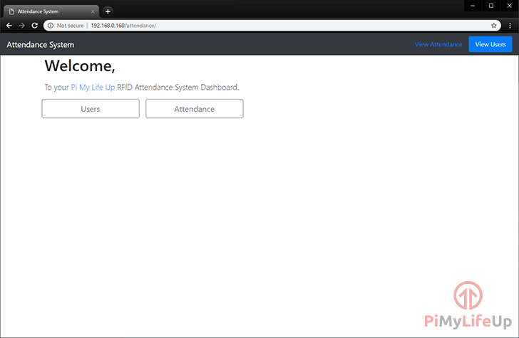
http://192.168.160/attendance6. Upon going to the website, you will be greeted by the following webpage, from here you can either check out your current users by clicking “Users” or viewing the attendance of users by clicking the “Attendance” button.
If you have gotten to this point, then everything is working as it should be and you should now have a basic RFID, and Raspberry Pi powered attendance system up and running.
Welcome Page
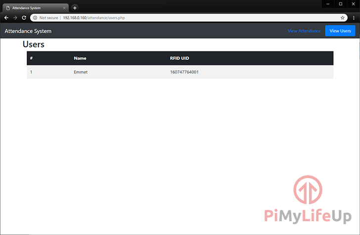
Attendance System Users Page
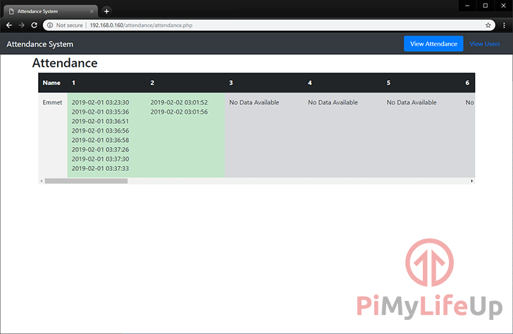
Attendance Page
Conclusion
The overall system is relatively basic but covers everything you need for a good attendance system. You can further extend both the backend and frontend to implement new features, a nicer user interface and much more.
I hope by now that you have a full working Raspberry Pi RFID attendance system. If you have some feedback, tips or anything else, then please don’t hesitate to leave a comment below.


Hello Emmet,
I am currently doing this build as a project for school, and I am running into an issue when setting up the initial configurations for the LCD display to operate correctly. I am unable to run the command as it is an externally-managed environment. My work around is to run , afterwards when I go to run I run into a Traceback error stating ModuleNotFoundError: no module name ‘Adafruit.GPIO’
Any assistance would be much appreciated. Thank you!
Hi Megan,
Do you know what sort of restrictions this managed environment has? You will need the ability to install several libraries to drive both the RFID chip as well as the screen.
Additionally, I still need to update this tutorial to work within a Python virtual environment for it to work with Raspberry Pi OS Bullseye.
Kind regards,
Emmet
Hello Emmet,
The set-up has been perfect so far but I’ve hit a roadblock at save_user.py. The end of the error when trying to run the script is as follows “mysql.connector.errors.ProgrammingError: Character set ‘utf8’ unsupported”. I’ve tried multiple solutions online, but none seem to be working. Do you have any thoughts on how to fix it?
Hi Uthvah,
It looks like something may have been broken in a recent release of the MySQL connector we are using, in particular when used in conjunction with MariaDB.
Can you please try using the following command to install the previous release and let me know if it solves the issues you are facing.
Will try and see if there is a better fix for this later, rather than relying on an older release.
Cheers,
Emmet
Yes, it works!!! Thanks a ton for the speedy response!