In this tutorial, we are going to take a look at the basics of the Raspberry Pi’s GPIO pins, also known as the general-purpose input and output pins.
These pins are essential for communicating with other circuitry, such as extension boards, custom circuits, and much more.
You can make some pretty cool stuff by using these pins with different extension boards and electronics. We will look into a lot more projects in the future that make use of these pins.
There is quite a bit to know about these pins, and I highly recommend that you follow this guide to understand them better before you start using them.
Also, be sure to check out our video on the Raspberry Pi GPIO pins located under the equipment list. It will take you through all the basics you need to know to get started.
Warning: Experimenting with the GPIO is risky and has a chance of bricking your Raspberry Pi. Knowing the power limitations of the GPIO pins and also understanding what you’re plugging in is a must.
Equipment
The equipment I use in this Raspberry Pi GPIO tutorial is listed below.
Recommended
- Raspberry Pi Amazon
- Micro SD Card Amazon (8 GB+ Recommended)
- Ethernet Cable Amazon or Wi-Fi Amazon
- 100 ohm resistor Amazon
- Red LED Amazon
- GPIO Breakout Kit Amazon
- Breadboard Amazon
- Breadboard Wire Amazon
Optional
- A Raspberry Pi Case Amazon with access to the GPIO pins
Video
Our video will take you through all the topics explained in this guide. If you learn better by listening and seeing, I highly recommend you check it out.
If you like the video, please subscribe to us or follow us on social media so you can stay up to date with all the coolest Raspberry Pi projects, guides, and more.
Raspberry Pi GPIO Diagrams
Now, let’s get started on this Raspberry Pi GPIO tutorial. We will be taking a look at the different types of pins available, how to enable the modules, what a breakout kit is, and finally, how to build and program a simple circuit.
If you own a Raspberry Pi B+, 2, Zero, 3, 4, or 5, you will have 40 pins in total. The super early models, such as the Raspberry Pi B, have just 26 pins.
See below for our Raspberry Pi GPIO pinout diagrams. We have included all three main iterations of the Raspberry Pi.
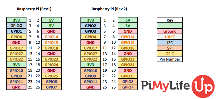
Raspberry Pi Revision 1 and 2
Our first diagram features the first two iterations of the Raspberry Pi, revisions 1 and 2. If you want a PDF version of this pinout diagram, you can find it for download here.
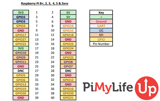
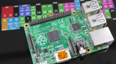
Raspberry Pi B+, 2, 3, 4, 5
The second diagram features the latest iterations of the Raspberry Pi. You will notice that the GPIO layout has not changed in some time.
The diagram below contains the Raspberry Pi B+, 2, 3, 4, 5, and the zero versions. If you want a PDF version of this diagram, you can find it for download here.
Pin Reference Guide
As you can see, there are more than just your standard pins. Some pins reference I2C, SPI, and UART.
- GPIO is your standard pins that can be used to turn devices on and off, such as an LED.
- I2C (Inter-Integrated Circuit) pins allow you to connect to and talk to hardware modules that support this protocol (I2C Protocol). This protocol typically takes up two pins.
- SPI (Serial Peripheral Interface Bus) pins can connect and talk to SPI devices. They are similar to I2C but makes use of a different protocol.
- UART (Universal Asynchronous Receiver/Transmitter) is the serial pins used to communicate with other devices.
- DNC stands for do not connect, this is pretty self-explanatory.
- The power pins pull power directly from the Raspberry Pi.
- GND are the pins you use to ground your devices. It does not matter which pin you use, as they are all connected to the same line.
All this might seem daunting at first, but it is pretty easy once you get going. A lot of the abbreviations and technical jargon make it easy to turn people off straight away.
Configuring and using the Pins
In this section, we will briefly touch on how to set up the pins so you can use them on the Raspberry Pi. We will cover more programming and using the pins in future Raspberry Pi projects.
In this example and future projects, we will be using Raspberry Pi OS. If you have not installed it, you can find out how to install the latest version by following my Raspberry Pi OS installation guide.
Configuring GPIO
If you are using the latest version of Raspberry Pi OS, you can start programming and using the GPIO pins without needing to do any extra configuration.
I recommend updating your Pi to the latest packages before proceeding. If you have not done this, then you can do it by running the following commands.
sudo apt update
sudo apt upgradeCopy
If you do not have the GPIO package installed, you can install it by running the following command.
sudo apt install rpi.gpioCopyConfiguring Raspberry Pi I2C
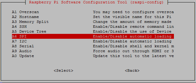
Setting up the I2C pins on the Raspberry Pi is super easy and will only take a couple of minutes.
Firstly, go to the Raspi-Config tool by entering the following command.
sudo raspi-configCopyHere, go to Interface Options and then to I2c. Enable I2c by selecting Yes.
The Pi should now alert you that I2C will be enabled after reboot. It will then ask if you want it to be loaded by default. Select yes if you plan on using I2c every time the Raspberry Pi boots.
Now we want to make sure it has successfully enabled the necessary modules. To do this, enter the following command.
lsmod | grep i2c_CopyThis command will return any modules that are running, starting with i2c. It should return something like this i2c_BCM2708.
Configuring Raspberry Pi SPI
Configuring the Raspberry Pi SPI is very similar to the I2c and is super easy, it will only take a couple of minutes.
Firstly, go to the Raspi-Config tool by entering the following command.
sudo raspi-configCopyOnce the config tool has loaded, go to Interface Options, and then to SPI.
Enable SPI, and it will tell you that it will be enabled after reboot. After that, it will ask if you want it to be loaded by default. Only select Yes if you plan on using it every time the Pi boots up.
To check that SPI is successfully up and running use the following command.
lsmod | grep spi_CopyThis command will return any modules that are running, starting with SPI. It should return something like spi_bcm2835. Make sure you have restarted your Pi before checking to see if the module has been loaded.
Using a Breakout Kit
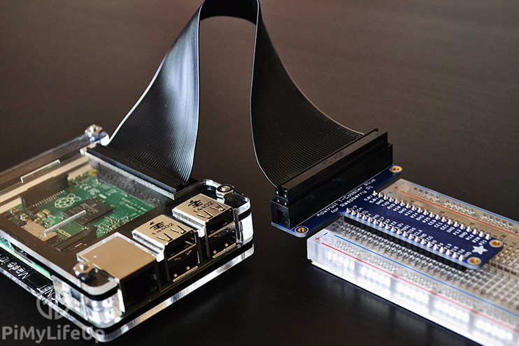
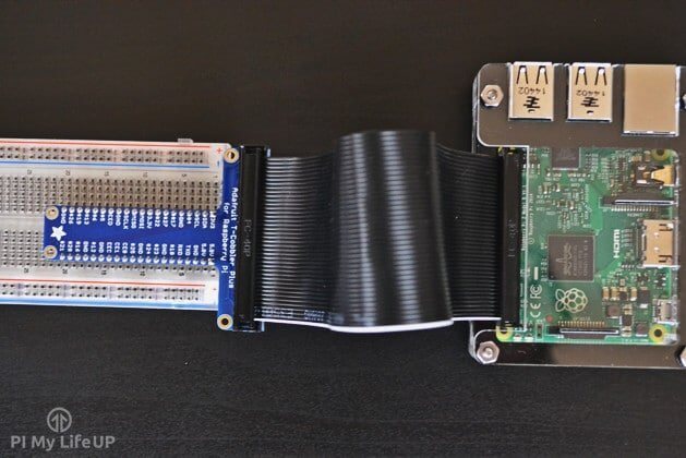
A breakout kit allows you to take all the pins via a ribbon cable and connect them to a breadboard or a different device. This kit makes it a lot easier and safer than working in and around the Raspberry Pi.
There are a few different types of breakout kits that you’re able to buy for the Raspberry Pi GPIO pins.
Personally, I prefer the T-type as they are easy to read and use. If you’re looking for a breakout kit to buy, then be sure to check out the equipment list above.
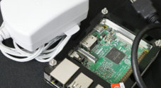
When connecting the ribbon cable, you must ensure it is connected, so it faces away from the board. You can see an example of a correct setup ribbon cable with a T-type breakout board right below.
Programming with the Raspberry Pi GPIO Pins
Programming with the GPIO pins on the Raspberry Pi is typically done using the programming language Python. This particular circuit and code are super easy to get going and won’t take you long at all to complete.
GPIO BOARD VS. GPIO BCM
There is a massive difference between the board and bcm modes. It is up to you which one you want to use for your project. Both modes have their own pros and cons.
GPIO board (GPIO.Board) references the physical numbering of the pins. For example, the top left pin is 1, and the top right pin is 2. It continues to count upwards as you go from top to bottom until you run out of pins. In our diagram, you can see this numbering in the middle of each group.
GPIO BCM (GPIO.BCM) is the Broadcom Soc Channel numbering. In the diagram above, you can find the number after GPIO. For example, on the Raspberry Pi 5, the pin below 3v3 is GPIO2, so the number for this pin is 2 in BCM mode.
A downside to BCM is that they have changed between versions (Raspberry Pi Rev 1 vs Raspberry Pi Rev 2) and may do so in the future. If you want to be safe, I recommend sticking to GPIO Board, but as I said earlier, it’s up to you how you want to reference the pins.
The Code for a Simple LED Circuit
If you’re happy to code and learn lots about Python, check out my example below.
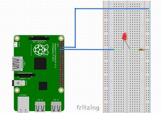
1. First, let’s set up our little circuit. I have a helpful, easy diagram to follow below. If you have a breakout kit, the circuit will obviously be a bit different since your wires will come from the cobbler.
Alternatively, simply connect the positive end of an LED up to pin 7 (GPIO4) and the negative end to a 100-ohm resistor that connects to a ground pin.
2. Now, create a Python file so that we can type out our Python script.
sudo nano led_blink.pyCopy3. Let’s write out a little script. It’s important to remember Python is whitespace sensitive.
For example, in the for loop, make sure you have four spaces for anything within the loop. To explain a little further, the GPIO.output(7, true) line will need to have four spaces before it.
#import the GPIO and time package
import RPi.GPIO as GPIO
import time
GPIO.setmode(GPIO.BOARD)
GPIO.setup(7, GPIO.OUT)
# loop through 50 times, on/off for 1 second
for i in range(50):
    GPIO.output(7,True)
    time.sleep(1)
    GPIO.output(7,False)
    time.sleep(1)
GPIO.cleanup()Copy
4. Now exit and save by pressing CTRL + X and then Y.
5. If you run the script, the circuit should come to life. You can run a Python script by entering the following command into the terminal. It is also important that you run it as the superuser using sudo.
sudo python led_blink.pyCopy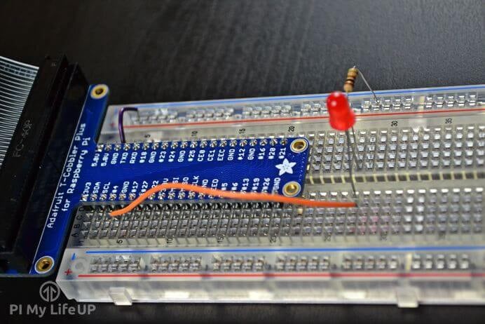
Conclusion
I hope this tutorial has helped introduce you to the basics of the GPIO pins and given you some ideas on how you can utilize them in your next project.
As I mentioned earlier in this guide, I will be doing a lot of projects that use the Raspberry Pi GPIO pins in the future. This range of projects includes using motion sensors, temperature gauges, controlling motors, and much more. You can find these projects in our Raspberry Pi sensors category.
If you have any questions, feedback or if I missed anything, then feel free to drop us a comment below.


For those of you wondering how to identify the positive end (Anode) and negative end (Cathode) of the LED, it is the longer leg and the shorter leg respectively.
The tutorial was great. Big help. Thanks.
Does the Rasberry Pi have any analogue inputs?
I am looking for a micrcontroller for a little control system which requires a few thermocouples.
My background is very similar to Richard above, I was once an embedded programmer for industrial controllers, now retired so I have time to play with my own projects but am not familiar with the current state of the art.
There’s no a/d converter on board, but you can likely buy a board for that, Steve.
If your requirements aren’t for it to be too precise, and you want something simple, you could devise a simple circuit based on the time it takes to charge a capacitor up to some level that raises a flag to an input pin. That might be good for determining say, a set level reached. You can use a 555 timer chip, they’re cheap and very useful for lots of things, and circuits for using them abound on the web. You turn on an output that via relay or opto-isolator puts a voltage on a capacitor through a resistor. The RC time-constant determines the time it takes to trigger an input on. Your interface can be simple as a couple transistors, depending on what you’re doing. The time required to reach the trigger point is determined by the voltage so you get an analog of an analog. But you can get as complex as you need to, with multiple channels of analog input going into an analog switch, sample-and-hold, to an a/d converter chip, then digital output read from that. There are likely circuits on the web for whatever U need. I do seem to remember there’s another Pi-ish board not sure if it’s an Arduino or another one I can’t seem to recall the name of, that does have a built-in a/d converter maybe 10 bit, with a few analog inputs. Cheers, happy hunting & happy new year!
take a look at DS18B20 digital temperature sensor that works with one wire protocol. I use then with PIC an it works like a charm
Thanks for the tutorial! I was hoping to control multiple solenoids (about 5) with the raspberry pi to press physical buttons. Do you have any tutorials that may help with that or at least give me a place to start?
With about 5 versions of the Pi out there, and as a newbie to Pi but not to programming (I’ve programmed professionally but am now retired) I am both blown away with the capabilities of my Pi 3B+ and totally frustrated by the lack of information on it’s hardware. A company whose main reason for creating it as an educational tool refuses to furnish it’s customers a detailed programmers model of its I/O map and address versus other models it sells? No programmer’s reference manual for their own hardware? Unbelievable!
But at least you furnish us with some cautions on not destroying our gpio interface, giving us a current limit on outputs, and warnings about not inputting inputs with over 3V. I have searched the web in vain for any assurance that the base address and offsets, and registers and bits for gpio are the same as for the Pi 2, too much lost time spent looking! Is that all a corporate secret, is such information holy, to be known only by high priests of the temple?
I’ve programmed in Forth, assembler, C and even Basic when it was the right tool, on a variety of systems, usually on the interface end of things, where bits turn on solenoids and motors etc., but have never in my life seen such lack of information by any manufacturer. It has to be totally intentional, no mistake.
Usually the manufacturer was your best ally, for example Intel’s wonderful manuals & guides on the 80C186 and 80C188 embedded machines… they WANTED you to succeed with their hardware. Maybe this mfg. wants to see confusion, that way you keep buying more until you find limits by yourself?
Gee, that to me, is antithetical to education or freedom. Maybe I need to get arduino clone & play. At least I’ve learned to like Linux, finally. And stand in awe of the Pi 3, really, I’m just frustrated. I’d like to do some Forth and assembler, explore the world of the quad-core processor, so far haven’t even found a full instruction set, programmer’s reference guide, no bare-metal stuff at all!
So can you assure me that if I use Python3, pretty friendly and C-like so far, will not fry anything on my Pi3B+?, are the base adress, offsets and registers & the control bits the same as the RPi2? Blasting bits off into the wrong registers or device in error can fry hardware, pfft, it’s gone, bye-Pi : )
Last but not least, thanks for your tutorial, one of the best I’ve seen on the web.
Feel your pain.
Tell me something please Gus. Instead of the LED I have a 5v relay i would like to use, I believe this should work? with or without the resistor?
make sure you include a diode like 1N4148 in parallel with relay coil otherwise you may damage the driver cct.
what about Pi zero?
Hi Omar,
Pi Zero, has exactly the same pin layout as the Raspberry Pi 2, 3, A+ & B+.
I will be updating this page soon to reflect this.
Hi,
nice guide. I am new to electronics and my question would be:
Does it make a difference where I plug in the resistor (between power source (pin 7) and LED or after LED to GND)?
How would you know, that you need an 100 Ohm Resistor?
A red LED likes to have about .02 amps of power (20 milliamps) at about 1.2 volts so if you have a 3.3 volt power source (pin 7) and a device (the red LED) that needs 1.2 volts then you have to select a resistor that will regulate the amperage flow so as to not blow up the Raspberry pi. Since we really are trying to regulate the left over voltage (3.3volts-1.2volts=2.1volts) then the 100 ohm resistor would create about .021 amps through the LED which is ideal. the math to calculate amps is voltage/ohms so 2.1 volts/100ohms equals .021 amps (21 milliamps). The math is a bit daunting but really most guys just toss a 100 ohm resistor in when working on these red LEDs and even less if working on a blue or white or ultraviolet LED since they like to run at a higher voltage, something like 1.8-3.0 volts. I’ve used resistors ranging from 80 ohms to 2000 ohms in the same sort of circuit but you will find that the higher the resistor ohmage (is that a word.) then the dimmer the light. Hope this helps.
Am I right that you can drive 17 leds at the same time? So all yellow pins? That should be an alternative for me instead of using an Arduino with 2 shift register.
You can control 12 LEDs with just 4 GPIO pins if you Charlieplex them. Look it up on the net. This is a really fun thing to do as a project. I built a 12 LED bar graph using just the 4 pins but with 5 you could control 20 LEDs.
I have typed in the Python code exactly as shown and followed all the steps.
When I type
sudo python led_blink.pyI get the message:
Traceback (most recent call last):File "led_blink.py", line 1, in
import RPI.GPIO as GPIO
ImportError: No module named RPI.GPIO
Hi Tom,
The i in “RPI.” should be lower case, this might be causing the issue above.
If that doesn’t fix then please let me know and I’ll look further into it.
I always call that the Peter’s Principle of Programming! You look at it a hundred times and don’t see the mistake and somebody else looks and goes, “It’s right there.”
Thanks Gus.
I got the same thing, it’s because the module is RPi.GPIO not RPI.GPIO lower case ‘i’ at the end of “RPi” –
My problem is that I’ve got no idea what a 100 hom resistor even looks like 🙁
I could tell you the resistor color code, but that’d be pointless. There is a color code, google is your friend.