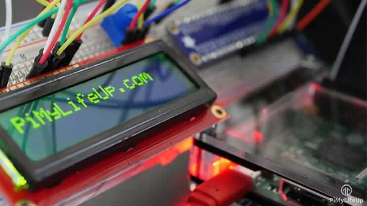
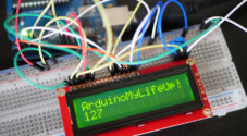
In this tutorial, I go through the steps on how to set up a Raspberry Pi LCD 16×2 display.
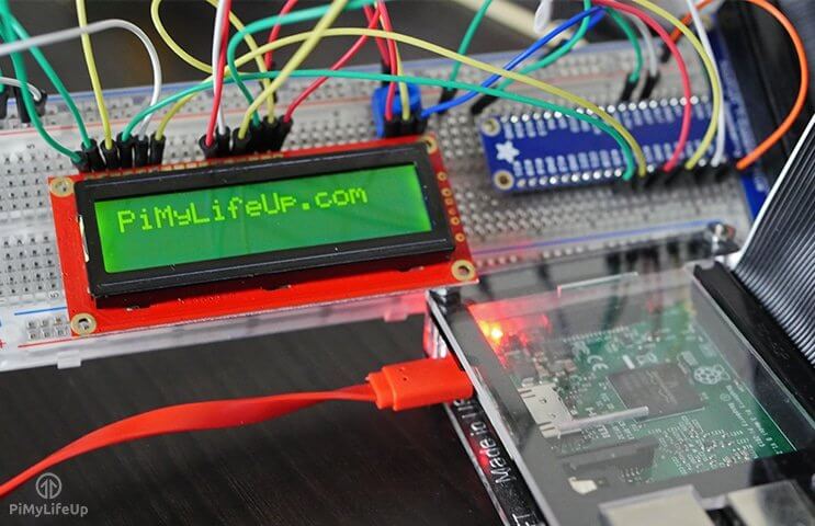
This display is a cool way to display some information from the Pi without needing any expensive or complicated display setup.
A 16×2 display unlike a touchscreen or a regular LCD screen is best used to display short messages or information.
You will find it extremely handy when you only need to display some essential data but don’t really need anything too large and expensive.
This tutorial will go through the basics of getting the screen setup and is incredibly handy for anyone who is entirely new to circuitry.
Equipment List
The equipment that you will need for this Raspberry Pi LCD tutorial is listed below.
Recommended
- Raspberry Pi Amazon
- Micro SD Card Amazon
- 16×2 LCD Amazon with Header Pins Amazon
- 10k Ohm Potentiometer Amazon
- Breadboard Amazon
- Breadboard Wire Amazon
Optional
- Raspberry Pi Case Amazon
- GPIO breakout kit Amazon
- USB Keyboard Amazon
- USB Mouse Amazon
- Ethernet Cable Amazon or Wi-Fi Amazon
Video Tutorial
If you prefer to watch and listen on how to setup the 16×2 LCD display with your Raspberry Pi, then you can check out the video below.
This video will walk you through all the written steps that we have below and will show you visually how everything should be wired.
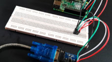
The Raspberry Pi LCD 16×2 Circuit
It may look like that there is quite a bit to this circuit, but basically it just involves connecting the wires up correctly to and from the display.
The potentiometer that’s in the circuit is essential for controlling the screen brightness. If you do not have one, then you can try swapping this out for a resistor. If you do use a resistor, then try using anything between 5k and 10k ohms. You may need to try out a few different values before getting the perfect resistance.
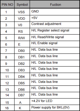
A typical 16×2 LCD display has 16 pins, but not all of them need to be used. In this circuit, we will only need to use 4 of the data bus lines since we’re just going to use it in 4-bit mode.
You will find that most 16 connector displays will be using an HD44780 controller. This controller makes the display pretty versatile and can be used across a wide range of devices. For example, this display I have used previously in an LCD tutorial for the Arduino.
The typical pin layout of the LCD board can be found below.
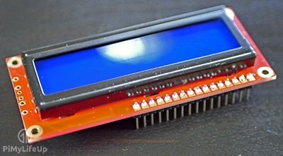
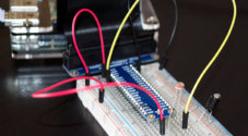
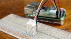
Assembling the 16×2 LCD
You will find that most 16×2 displays do not come with the header pins pre-soldered.
This lack of soldering means you will need to solder some header pins on before you can use it. It’s extremely hard getting a good connection to the screen without them. Soldering is a pretty straightforward task and should only take a few minutes for anyone who has soldered before.
1. First, snap the header pins, so you have 1 line of 16.
2. Place the header pins up through the holes of the display. The short side of the header pins should stick up.
3. Now using a hot soldering iron and some solder, slowly solder each of the pins.
4. It’s now ready for use.
Connecting Everything Up
Connecting the 16×2 LCD display to the Raspberry Pi is pretty straightforward. There will be quite a few wires to connect up, but there isn’t anything overly complex.
There is one thing that you should be aware of before you jump in and start assembling the circuit. Since we do not want 5v feeding back into the Pi (Pi’s GPIO pins are rated 3v3) we will need to make the read/write pin of the LCD go to ground.
In the steps below the physical/logical numbering of the pins are in the brackets otherwise it’s the GPIO numbering.
1. Place a wire from 5v (Pin 2) to the positive rail on the breadboard.
2. Place a wire from ground (pin 6) to the ground rail on the breadboard.
3. Place the 16×2 display onto the breadboard.
4. Place the potentiometer onto the breadboard.
5. Connect the positive and ground pins to the relevant rails on the breadboard.
Starting from pin 1 of the LCD display do the following or simply refer to the circuit diagram below. Pin 1 of the screen is the pin closest to two edges of the board.
1. Pin 1 (Ground) goes to the ground rail.
2. Pin 2 (VCC/5v) goes to the positive rail.
3. Pin 3 (V0) goes to the middle wire of the potentiometer.
4. Pin 4 (RS) goes to GPIO25 (Pin 22)
5. Pin 5 (RW) goes to the ground rail.
6. Pin 6 (EN) goes to GPIO24 (Pin 18)
7. Pin 11 (D4) goes to GPIO23 (Pin 16)
8. Pin 12 (D5) goes to GPIO17 (Pin 11)
9. Pin 13 (D6) goes to GPIO18 (Pin 12)
10. Pin 14 (D7) goes to GPIO22 (Pin 15)
11. Pin 15 (LED +) goes to the positive rail.
12. Pin 16 (LED -) goes to the ground rail.
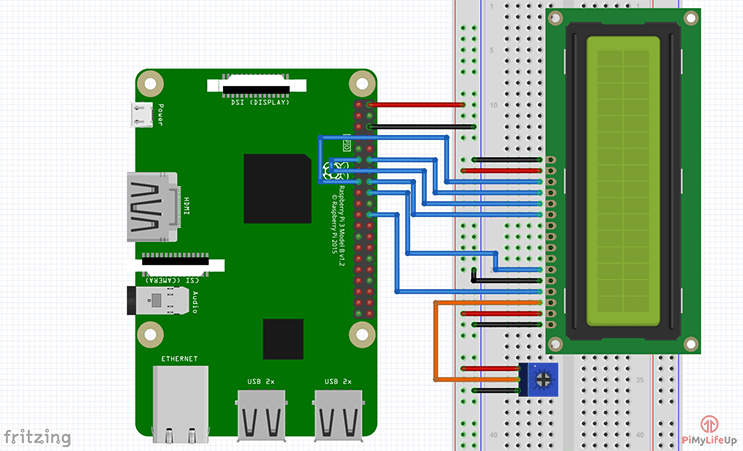
That’s all you need to do, and the screen should now be able to turn on and communicate with the Raspberry Pi without any issues. If you’re having trouble connecting the display, then refer to the circuit diagram below.
Code to communicate with the 16×2 Display
On the latest version of Raspbian, all the required packages are pre-installed for communicating with GPIO devices. You should also find that Python is already installed.
If you’re running an older version of Raspbian than it might be worth checking out more information on setting up the Pi for GPIO usage.
Having a basic understanding of Python will make your life a lot easier, with that said, this tutorial should be fine without any prior Python experience.
Required Library
In this example, I am going to install and use the library from Adafruit. It’s designed for Adafruit LCD boards but will also work with other brands as well. If your display board uses an HD44780 controller, then it should work with no issues at all.
First, clone the required git directory to the Raspberry Pi by running the following command.
git clone https://github.com/pimylifeup/Adafruit_Python_CharLCD.gitCopyNext change into the directory we just cloned and run the setup file.
cd ./Adafruit_Python_CharLCD
sudo python setup.py installCopy
Once it’s finished installing you can now call the Adafruit library in any Python script on the Pi.
To include the library just add the following line at the top of the Python script. You can then initialize the board and perform actions with it.
import Adafruit_CharLCD as LCDCopyCommunicating with the Display
Communicating with the Raspberry Pi LCD 16×2 display is very easy thanks to the library provided by Adafruit. It makes it incredibly easy to write Python scripts to setup and alter the display.
In the folder that we just downloaded there are a few examples of how to use the LCD library. It’s important that before you run any of these examples that you update the pin variables at the top of the file. If you followed my circuit the values below are the correct ones.
lcd_rs        = 25
lcd_en        = 24
lcd_d4        = 23
lcd_d5        = 17
lcd_d6        = 18
lcd_d7        = 22
lcd_backlight = 4
lcd_columns = 16
lcd_rows = 2Copy
If you want to check out one of the examples simply open up the file by entering the following.
cd ~/Adafruit_Python_CharLCD/examples/
sudo nano char_lcd.pyCopy
In here update the pin configuration values to the ones listed above. Once done, simply exit by pressing CTRL + X then Y.
Now to run this code simply enter python followed by the file name (including the extension).
python char_lcd.pyCopyFunctions and Python Code
I will go through some of the most important methods that you will need to know about interacting with the screen using Python.
To initialize the pins, you will need to call the following class. Make sure all the variables that are being passed as parameters are defined before calling the class.
lcd = LCD.Adafruit_CharLCD(lcd_rs, lcd_en, lcd_d4, lcd_d5, lcd_d6, lcd_d7, lcd_columns, lcd_rows, lcd_backlight)Once that’s done you can then change the display to however you need it. I will quickly go through some of the methods that are available to you using the Adafruit library.
home() – This method will move the cursor back to home which is the first column on the first line.
clear() – This method clears the LCD so that it’s completely blank.
set_cursor(col, row) – This method will move the cursor to a specific position. You specify the position by passing the column and row numbers as parameters. Eg. set_cursor(1,4)
enable_display(enable) – This enables or disables the display. Set it to true to enable it.
show_cursor(show) – This either shows or hides the cursor. Set it to true if you want the cursor to be displayed.
blink(blink) – Turns on or off a blinking cursor. Again set this to true if you want the cursor to be blinking.
move_left() or move_right() – Moves the cursor either left or right by one position.
set_right_to_left() or set_left_to_right() – Sets the cursor direction either left to right or right to left.
autoscroll(autoscroll) – If autoscroll is set to true then the text will right justify from the cursor. If set to false it will left justify the text.
message(text) – Simply writes text to the display. You can also include new lines (\n) in your message.
There are a few more methods available, but it’s unlikely that you will need to use them. If you want to find all the methods that are available then simply open up the Ardafruit_CharLCD.py file located within the Adafruit_CharLCD folder, this can be found in the Adafruit_Python_CharLCD folder.
sudo nano ~/Adafruit_Python_CharLCD/Adafruit_CharLCD/Ardafruit_CharLCD.pyCopyBelow is a straightforward script that I have put together that allows the user to input text that is then displayed on the screen.
#!/usr/bin/python
# Example using a character LCD connected to a Raspberry Pi
import time
import Adafruit_CharLCD as LCD
# Raspberry Pi pin setup
lcd_rs = 25
lcd_en = 24
lcd_d4 = 23
lcd_d5 = 17
lcd_d6 = 18
lcd_d7 = 22
lcd_backlight = 2
# Define LCD column and row size for 16x2 LCD.
lcd_columns = 16
lcd_rows = 2
lcd = LCD.Adafruit_CharLCD(lcd_rs, lcd_en, lcd_d4, lcd_d5, lcd_d6, lcd_d7, lcd_columns, lcd_rows, lcd_backlight)
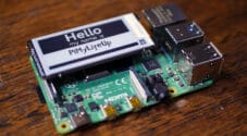
lcd.message('Hello\nworld!')
# Wait 5 seconds
time.sleep(5.0)
lcd.clear()
text = raw_input("Type Something to be displayed: ")
lcd.message(text)
# Wait 5 seconds
time.sleep(5.0)
lcd.clear()
lcd.message('Goodbye\nWorld!')
time.sleep(5.0)
lcd.clear()CopyIf the display isn’t showing anything when your Python script is running, then it’s likely the pins defined in your script are wrong. Double check these and also double check the connections on the breadboard.
Further Work
This tutorial covers the basics of setting up the 16×2 LCD display correctly with the Raspberry Pi.
There is just so much more you’re able to do with this cool display. For example, you can have a script launch on boot that can display specific values such as IP address, time, temperatures and so much more.
There is also a huge range of cool sensors that you should try incorporating with this display. Something like the DS18B20 temperature sensor would work great with the display. Simply update the display every few seconds with the new temperature.
I hope this tutorial has helped you with setting up a Raspberry Pi LCD 16×2 display. If you notice a mistake, come across an issue or anything else, then please do not hesitate to leave a comment below.
what is the code to show the distance? from this project: https://pimylifeup.com/raspberry-pi-distance-sensor/
The code below should display the distance on the LCD (I haven’t tested it). Of course, you will need all the extra code for preparing the LCD for data.
distance_text = "Distance:",distance,"cm"

lcd.message(distance_text)

time.sleep(5.0)

lcd.clear()
Problem: My LCD 16*2 lights up and does not display any characters although all the wiring is correct.
Solution: I just connected (pin 3) of LCD to Ground (GND) without use of potentiometer and it worked.
Same thing ahppened to me. I solved it by adjusting 10Kohm potentimeter.
Put the backlight on the pin specified in example (4) and backlight does not work as it should. Is this a bug in the library or something else?
Hi Joe,
Do you mind explaining a bit more about whats not working with your backlight?
Cheers,
Emmet
Hey can anybody help i have a small problem it all goes ok until i get to this
""import Adafruit_CharLCD as LCD
""
it returns this
""
pi@raspberrypi:~ $ import Adafruit_CharLCD as LCD
bash: import: command not found
""
so i’m at a stand still until i can get it fixed it’s probably just me doing something wrong.
I asked this before but it didn’t post so i hope this is ok really need help thanks!
Hi Jordan,
That line is to be used inside Python scripts whenever you need to use the Adafruit LCD library. If you move onto the section called “communicating with the display” it shows a example. (char_lcd.py)
Hi,
Great tutorial.
Got everything working except that the backlight does not turn off
when using the example program.
I have double checked my wiring.
Any ideas.
Thanks
hello,
thanks for your tutorial.
what should i do if i want to display a variable’s content on the 16×2 lcd?
like for example i have a string stored in variable f.
so how would i proceed to print contents of f?
since you showed the displaying of user entered data.
i am using python language.
your help would be much appreciated.
many thanks. 🙂
lcd.message(str(nameOfVariable))should workHI
WHen I run the install it works fine, I can start Python3 but can only import the module if I’m in the /usr/local/lib/python2.7/dist-packaged folder. Can you help me sort this out so that the library is in my path directory?
Thank you
Mark
Minor Typo in the Methods section…the word set…
set_right_to_left() or et_left_to_right() – Sets the cursor direction either left to right or right to left.
FYI
thank you, fixed it.