In this Raspberry Pi pressure pad tutorial, I will go through the steps of connecting a force sensitive resistor to the Pi.
There are many uses for a pressure pad, such as detecting when someone sits down or places pressure on a specific part of an object. It is a pretty great sensor to make use of in IoT projects and more.
In this tutorial, we go through the steps of connecting the force sensitive resistor, so you can detect if enough pressure has been applied or not. We will also go through methods to receive variable values by using a capacitor or an analog to digital converter (ADC).
The first design, is the simplest and will only tell you whether there is pressure or not.
The second design in this tutorial makes use of a capacitor just like in the LDR tutorial. Using this method, we can measure the resistance of the pressure pad. If there is no pressure, we will get almost no values. As soon as we apply some pressure, we will get values varying from high as 100,000+ right down to 5,000.
The third design that I make use of in this tutorial uses an ADC. By using an ADC, we will be able to get variable values from the pressure pad. Perfect if you’re programming software that does something at different pressure points.
You can find the full tutorial to set up a pressure pad right below.
Equipment
Below is the full list of equipment that you will need to complete this Raspberry Pi pressure pad tutorial.
Recommended
- Raspberry Pi Amazon
- Micro SD Card Amazon
- Ethernet Cable Amazon or Wi-Fi Amazon
- Power Supply Amazon
- Breadboard Amazon
- Breadboard Wire Amazon
- Pressure Pad Amazon
- 1m ohm Resistor Amazon
Optional
- MCP3008 Amazon or similar
- 1uf Capacitor Amazon
- Raspberry Pi Case Amazon
- USB Keyboard Amazon
- USB Mouse Amazon
- GPIO Breakout Kit Amazon
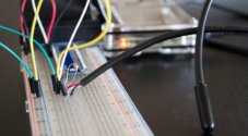
Circuit
The circuit for this pressure pad is surprisingly simple. Firstly, I will touch on the parts that make up the circuits and why we’re making use of them.
Keep in mind that you won’t need all the parts as it just depends on what you plan on doing.
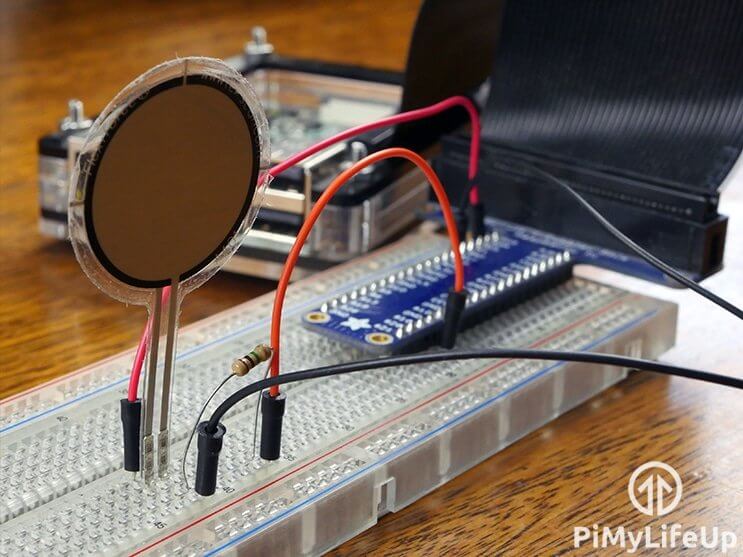
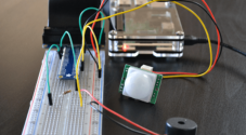
Pressure Pad Sensor
The pressure pad is the most important part of our circuit, as it won’t work without it in use. I made use of a FlexiForce pressure pad sensor, but you’re able to use cheaper alternatives.
The FlexiForce sensor resistance will be near-infinite when you’re applying little to no pressure. If you’re applying a lot of pressure it will go down to under 25k ohms.
It’s very much like a light-dependent sensor, but instead of the surrounding light, it uses direct pressure.
Resistor
The resistor is required in all our circuits except for the capacitor circuit. This resistor will act as a voltage divider and divides the 3v3 between the pressure pad and the resistor. When pressure is applied, it will provide enough voltage to send our pin to high.
Below is the equation that you can use to work out what the voltage out to our GPIO pin will be. For example, if our pressure pad is max resistance, it will be (1,000,000 / (1,000,000 + 10,000,000)) * 3.3 = 0.3 volts. This voltage isn’t enough to send the pin to high.
On the flip side, if we’re applying a high amount of pressure so the pressure pad resistance is only 50,000 then our equation will be (1,000,000 / (1,000,000 + 50,000)) * 3.3 = 3.14 volts. This voltage is enough to send the pin to high.

To learn more about voltage dividers, I recommend checking out our guide on them.
Since the Raspberry Pi doesn’t have analog pins, it will only ever be high or low. We can work around this by either using a capacitor or analog to digital converter, see below.
Capacitor
A capacitor will allow us to get variable results without the use of an analog to digital converter. The results aren’t as accurate but still incredibly handy as you can see the varying amount of pressure being applied to the pressure pad.
The capacitor will act as a battery charging up while receiving power and discharging when it’s full or when it stops receiving a charge. By using this in series with our pressure pad, we can work out the resistance of the pressure pad. Higher the resistance, the less pressure is being applied.
Analog to Digital Converter
An ADC allows us to connect analog sensors and devices to the Raspberry Pi. It involves quite a bit more wiring but will allow us to get a variable value rather than a simple on or off.
A variable value allows us to do more such as checking how much pressure is being applied and performing a different function depending on the result. Great if you need to keep an eye on the pressure on specific areas.
I won’t go much into the ADC in this tutorial, so if you want to learn more, then be sure to check out my tutorial on using an ADC with the Raspberry Pi.
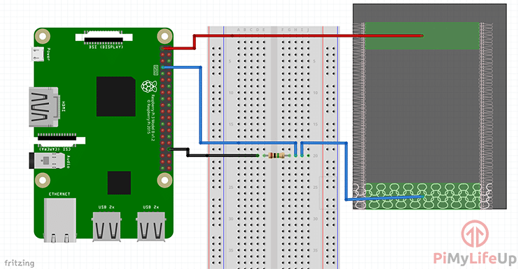
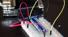
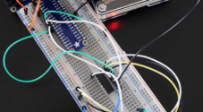
Circuit Diagram using a Resistor
The steps to set up this circuit are straightforward and should not take you long at all. This circuit will give you a simple on or off result from the pressure pad.
- Connect one end of the pressure pad to 3v3.
- Place a 1.0M Ohm resistor onto the breadboard and have one end go to GND and the other to pin 7.
- Lastly, have the resistor end that goes to pin 7 also go to the other end of the pressure pad.
The diagram below shows you how it should look.
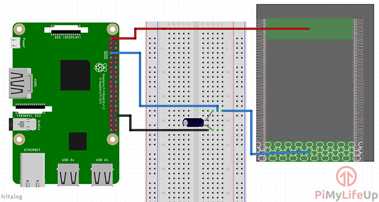
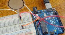
Circuit Diagram using a capacitor
We can use a capacitor to measure the resistance of the pressure pad. This circuit is ideal if you need to know roughly how much pressure is being applied to the sensor.
- Connect one end of the pressure pad to 3v3.
- Place a 1uf capacitor onto the breadboard and have the negative end go to GND and the other to pin 7 and the pressure pad.
If you need more information, then please refer to the diagram below.
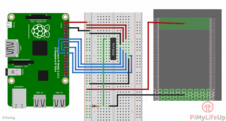
Circuit using an Analog to Digital Converter
The last circuit we’re looking at makes use of an analog to digital converter. This will allow you to get semi-accurate values from the pressure pad. We also make use of the resistor and use it as a voltage divider.
- VDD (Pin 16) wire this to 3.3V
- VREF (Pin 15) wire this to 3.3V
- AGND (Pin 14) wire this to ground
- CLK (Pin 13) wire this to GPIO11 (Pin 23/SCLK)
- DOUT (Pin 12) wire this to GPIO9 (Pin 21/MISO)
- DIN (Pin 11) wire this to GPIO10 (Pin 19/MOSI)
- CS (Pin 10) wire this to GPIO8 (Pin 24/CE0)
- DGND (Pin 9) wire this to GROUND
- Wire the pressure pad to 3v3
- Wire a 1.0k Ohm resistor from GROUND to CH0
- Also, wire CH0 to the pressure pad
If you require clarification on the steps above, observe the diagram below.
Coding the Pressure Pad
Each circuit setup requires its own unique code. The simplest is using the resistor, while the most complicated is to use an analog to digital converter.
To gain a better understanding of Python, I recommend checking out our Python syntax guide and our introduction to Python.
Code using a Resistor
Much like the circuit, the code for the resistor is also easy since we’re only looking for when the pin goes to high.
In the code, we import our required packages, RPi.GPIO, for interaction with the GPIO pins and time for pausing the script.
import RPi.GPIO as GPIO
import time
Now we first set up the GPIO so that it runs in BCM mode and setup GPIO pin 4 to act as an input.
GPIO.setmode(GPIO.BCM)
GPIO.setup(4,GPIO.IN)
Next, we enter an infinite loop and read the GPIO pin. If it is high and the previous reading was low, then we print a message. We then pause the script slightly before repeating.
while True:
    #take a reading
    input = GPIO.input(4)
    #if the last reading was low and this one high, alert us
    if ((not prev_input) and input):
        print("Under Pressure")
    #update previous input
    prev_input = input
    #slight pause
    time.sleep(0.10)
You can get the full code for using a resistor right below.
import RPi.GPIO as GPIO
import time

GPIO.setmode(GPIO.BCM)
GPIO.setup(4,GPIO.IN)

#initialise a previous input variable to 0 (Assume no pressure applied)
prev_input = 0
try:
    while True:
        #take a reading
        input = GPIO.input(4)
        #if the last reading was low and this one high, alert us
        if ((not prev_input) and input):
            print("Under Pressure")
        #update previous input
        prev_input = input
        #slight pause
        time.sleep(0.10)
except KeyboardInterrupt:
    pass
finally:
    GPIO.cleanup()
Code using a Capacitor
Much like resistor code this isn’t overly complex and is based on our LDR code that we made use of in a previous tutorial.
Firstly, we must insert all the packages we require for this to work correctly, time, and GPIO.
import RPi.GPIO as GPIO
import time
The rest of our code is pretty simple, we have a function called rc_time, and this takes one parameter. In this function, we wait until the pin goes to high and then return the count where “count” is the time it took to go high.
Once we have returned the count we have the pin to act as an output and set it to low, we then wait 100ms before switching it back to an input. It will then count until the pin goes high.
You can use the count value to determine how much pressure somebody is applying to the pressure pad. If the value is really high such as 50k+, then you’re applying little to no pressure. Lower than 10k means there is quite a bit of pressure on the pad.
The full code is right below, or you can find it over on our GitHub.
#!/usr/local/bin/python

import RPi.GPIO as GPIO
import time

GPIO.setmode(GPIO.BCM)

#define the pin that goes to the circuit
pin_to_circuit = 4

def rc_time (pin_to_circuit):
    count = 0

    #Output on the pin for
    GPIO.setup(pin_to_circuit, GPIO.OUT)
    GPIO.output(pin_to_circuit, GPIO.LOW)
    time.sleep(0.1)

    #Change the pin back to input
    GPIO.setup(pin_to_circuit, GPIO.IN)

    #Count until the pin goes high
    while (GPIO.input(pin_to_circuit) == GPIO.LOW):
        count += 1

    return count

#Catch when script is interrupted, cleanup correctly
try:
    # Main loop
    while True:
        print(rc_time(pin_to_circuit))
except KeyboardInterrupt:
    pass
finally:
    GPIO.cleanup()
Code using an Analog to Digital Converter (ADC)
The analog to digital converter code is pretty straightforward, and the tricky part is receiving the value from the MCP3008 chip. If you want to know more about this code, check out on our analog to digital converter tutorial.
Below is the full code for using an MCP3008, you can also get it off our GitHub.
#!/usr/bin/python

import spidev
import time

#Define Variables
delay = 0.5
pad_channel = 0

#Create SPI
spi = spidev.SpiDev()
spi.open(0, 0)
spi.max_speed_hz=1000000

def readadc(adcnum):
    # read SPI data from the MCP3008, 8 channels in total
    if adcnum > 7 or adcnum < 0:
        return -1
    r = spi.xfer2([1, 8 + adcnum << 4, 0])
    data = ((r[1] & 3) << 8) + r[2]
    return data

try:
    while True:
        pad_value = readadc(pad_channel)
        print("---------------------------------------")
        print("Pressure Pad Value: %d" % pad_value)
        time.sleep(delay)
except KeyboardInterrupt:
    pass
You can also make use of something like Raspberry Pi Cayenne if you don’t wish to do any coding.
I hope by the end of this tutorial, you have a force sensing resistor connected to your Raspberry Pi.
If you have any feedback on this Raspberry Pi pressure pad tutorial, then please feel free to leave us a comment below.
Resistor method was easy and worked well for me! Thanks for the guide
Hello, whats the value of the resistor in the first method?
Thank you
Hi Othmane,
My apologies this is not mentioned! I believe it is a 1.0M Ohm resistor.
Is this possible with Raspberry pi3 instead of 4?
Hi Ayan,
You should be able to use this pressure pad project on any Raspberry Pi.
Cheers,
Emmet
whats the value of the capacitor in the second method???
It’s 1uf, and I’ll update the tutorial so that it mentions it in the instructions.
That was it. Thank you!
Hello, I am trying to get this to work with the a2d converter, and when i run the code i get this error
Traceback (most recent call last):
File “/home/pi/Desktop/force_sensor_test.py”, line 12, in
spi.open(0, 0)
FileNotFoundError: [Errno 2] No such file or directory
Do you guys have any advice? I have been trying to figure out the problem but i am new to python and cant figure it out.
Thanks
Hi Neil,
Do you have the SPI Interface enabled on your Raspberry Pi?
Cheers,
Emmet
The code for the a2d converter has an error. the max speed setting should not be commented out. took me 3 days to figure that one out.
Hi Neil,
Thank you for pointing out that mistype.
We have gone ahead and corrected that in tutorial.
Cheers,
Emmet