In this Raspberry Pi LED Strip tutorial, we will be showing you how to connect an APA102 RGB LED Strip to the Pi.
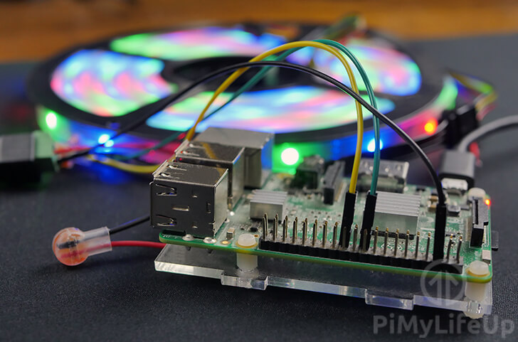
Alongside showing you how to connect the APA102 led strip to the Pi, we will also show you how to utilize the “apa102-pi” Python packages to interact with the strip and change the color of individual LEDs.
The APA102 is one of the few RGB led strips that can be easily used with the Raspberry Pi. This ease of use is thanks to it using the SPI protocol for its data, with one clock line and one data line.
One of the most significant advantages to the APA102 is that it is not as sensitive to timing. The lack of a need for critical timing is crucial for the Raspberry Pi as it is not excellent at maintaining critical timing.
You can extend this project further by utilizing a sensor or other devices to control the color of the LED strip. For example, you can a temperature sensor and have the color change depending on how hot or cold it is.
This tutorial should work with all versions of the Raspberry Pi except for the very first version as it’s pin layout is different.
Equipment
Below is all the equipment that you will need for connecting the APA102 RGB LED strips with the Raspberry Pi.
Recommended
- Raspberry Pi Amazon
- Micro SD Card Amazon
- APA102 LED Strip Amazon
- Female DC Power Adapter Jack Amazon
- 5V, 10A AC Power Adapter Amazon
- Breadboard wire Amazon
Optional
Wiring your APA102 LED Strip to the Raspberry Pi
Luckily for us, the APA102 LED strip is one of the few LED strips that can be wired to the Raspberry Pi easily thanks to the APA102 utilizing an SPI connection for control.
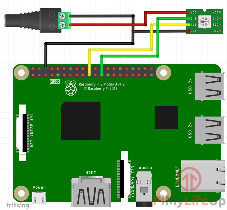
We have included both written instructions and a diagram to help you wire the APA102 LED strip.
- Wire the Positive Pin (+) of the DC Barrel Adapter to the VCC connection on the APA102.
- Wire the Negative Pin (–) of the DC Barrel Adapter to both Physical pin 6 (GND) on the Raspberry Pi and the GND connection on the APA102 LED strip.
- Wire the SDI (DI) connection of the APA102 to Physical Pin 19 (MOSI) on the Raspberry Pi.
- Wire the CKI (CI) connection of the APA102 to Physical Pin 23 (SCLK) on the Raspberry Pi.
If the written instructions above confuse you, then you should check out the diagram below as it shows where each connection should be going.
Ensure that you wire the ground connection from the APA102 LED strip to both the DC barrel adapter and the Raspberry Pi itself. If you don’t, then the LED strip will not work correctly as it requires both connections.
We utilize an external power source as the Raspberry Pi is not capable of providing the current needed for long LED strips. The required power draw could damage the Raspberry Pi.
Calibrating your APA102 using the Raspberry Pi
In this tutorial, we are making use of the latest version of the Raspbian operating system. For the best compatibility we recommend that you are running Raspbian.
1. The first thing we need to do before we start writing some code to control the APA102 is to update our Raspberry Pi by running the following two commands.
sudo apt-get update
sudo apt-get upgrade
2. With our Raspberry Pi’s operating system now up to date, we can now proceed to install Python 3 and its pip module.
To install the packages that we need to control our APA102 LED strip, run the following command.
sudo apt-get install python3 python3-dev python3-pip3. We can now go ahead and install the apa102-pi Python package.
This package is designed for the Raspberry Pi to handle all the grunt work for talking with and sending data through to the APA102 LED strip.
Install the APA102 Python package by running the following command.
sudo pip3 install apa102-pi4. Now that we have the “apa102-pi” Python packages installed to the Raspberry Pi, we can now write a basic Python script. We will be using this script to work our APA102’s color order.
Run the following command to begin writing a Python file that we will call “rgbcalibrate.py“.
nano ~/rgbcalibrate.py5. Within this file, enter the following lines of code. We will explain what each section does as we go along.
from apa102_pi.driver import apa102To start, we import the “apa102” library into our script. We will be utilizing this library to talk with our APA102 LED strip.
strip = apa102.APA102(num_led=150, order='rgb')Here we instantiate the apa102 library to our “strip” object. Into this, we pass in a couple of variables.
num_led – This variable defines the number of LEDs present in your strip. You can either manually count the LED’s or work it out by multiplying the number of LEDs per meter by the length of your strip in meters.
For example, the LED strip we are using is 5 meters long and has 30 LEDs per meter. Using a bit of math means that the number of LEDs for the entire strip is 150.
order – This variable defines the color order for the LED Strip, by default we will set this to ‘rgb‘. The purpose of this section is to work out whether that’s correct or not.
strip.clear_strip()Here we call the “strip” objects, “clear_strip()” function. This function will turn off all the LEDs in the strip and leave it completely blank.
strip.set_pixel_rgb(1,  0xFF0000)  # Red
strip.set_pixel_rgb(2, 0x00FF00)  # Green
strip.set_pixel_rgb(3, 0x00FF00)  # Green
strip.set_pixel_rgb(4, 0x0000FF)  # Blue
strip.set_pixel_rgb(5, 0x0000FF)  # Blue
strip.set_pixel_rgb(6, 0x0000FF)  # Blue
Next, we utilize the “strip” objects, “set_pixel_rgb()” function so that we can define the color to set for individual LEDs. These objects are pushed into a buffer.
The first argument in the “set_pixel_rgb” function defines the number for the LED that we are setting the color.
The second argument defines the color to set for the chosen LED. The color is set using a hexadecimal code. For example 0xFF0000 is pure red.
We utilize this code to set LEDs in the following order, one red, two green, and three blue. We are doing this to make sure that “rgb” is the correct color order for our APA102 LED strip.
strip.show()This function tells the APA102 library that it should now push the buffer we set with the “set_pixel_rgb()” function to the LED strip. This function is what will light up the LED strip.
strip.cleanup()Finally, before the script finishes executing, we need to run the strip object’s “cleanup()” function. This function cleans up all the connections and prepares it so that we can easily talk with the APA102 again.
6. Once everything has been entered into the file, it should look like what we have below.
Once you are happy everything is correct you can save the file by pressing CTRL + X then Y followed by ENTER.
from apa102_pi.driver import apa102

strip = apa102.APA102(num_led=150, order='rgb')

strip.clear_strip()

strip.set_pixel_rgb(0,  0xFF0000)  # Red
strip.set_pixel_rgb(1, 0x00FF00)  # Green
strip.set_pixel_rgb(2, 0x00FF00)  # Green
strip.set_pixel_rgb(3, 0x0000FF)  # Blue
strip.set_pixel_rgb(4, 0x0000FF)  # Blue
strip.set_pixel_rgb(5, 0x0000FF)  # Blue

strip.show()

strip.cleanup()
Testing the Python Script
1. Now that we have finished writing our “rgbcalibrate.py” script, we can now go ahead and run it by running the following command.
python3 ~/rgbcalibrate.py2. The APA102 Led strip should now have lit up. If the color order we specified is correct and everything is working as intended, you should see 1 red LED, 2 green LEDs, and 3 blue LEDs.
Assuming the color order was correct, then you have successfully wired up your APA102 led strip to the Raspberry Pi. There is nothing else that you need to do.
If the color order is not correct, make a note of it. For example, if the color order is blue, green, red, then make a note of this as “bgr” as you will need to modify the “rgbcalibrate.py” script slightly.
Within the script search for the “order='rgb'” line and change the ‘rgb‘ section of it to match the color order that was displayed on your LED strip.
You can verify that this change was correct by saving and rerunning the script and observing the color order now displayed on your LED strip.
As I mentioned earlier in this tutorial, there are plenty of uses for a Raspberry Pi RGB LED strip. For example, you can use it to display how much pressure is being applied to a force sensor. Red for large amounts of pressure, green for little to no pressure.
At this point, you should now have successfully connected your APA102 LED strip to your Raspberry Pi and tested a couple of LEDs using the “apa102-pi” Python library.
If you run into any issues or have some feedback, then feel free to drop a comment below.


A small correction in the ‘Testing the Python Script’ section:
– Step 2 says: ‘you should see 1 red LED, 2 green LEDs, and 3 red LEDs.’
– Should be: ‘you should see 1 red LED, 2 green LEDs, and 3 BLUE LEDs.
Thanks for this article, going to try it out.
Hi Jeff,
Thank you for pointing out that misake.
I haven now corrected it
Does this all work on Raspberry PI 4? If it does where do I wire everything?
Is it the same?
Hi Tom,
This project should work fine on the Raspberry Pi 4. Wiring should also remain the same as there was no significant changes in the GPIO pinss.
Cheers,
Emmet
Do I need to buy and wire everything before I start?
Yes
Why don’t you use any resistors? I thought you always have to use resistors to connect LEDs up to the GPIO pins of the Raspberry Pi. But maybe I’m just wrong.
Appreciate all your work. You’re doing a great job.
Hi Milena,
You do not need a resistor when connecting these LED’s as the APA102 chips handle the current limiting on it’s own.
So all you need to provide it is power and a data connection.
Cheers,
Emmet
More precise then Emmet’s answer: The Pi only sends a clock signal and a data signal to the LED Strip. Power is added throuch an extra powersupply, so you don’t drive the LEDs directly, you only tell the microcontroller on every LED pixel how bright every color should be.
Hi, two corrections I see to the above:
1) In the first bulleted list, the last two give swapped pin connections:
”
* Wire the CKI (CI) connection of the APA102 to Physical Pin 19 (MOSI) on the Raspberry Pi.
* Wire the SDI (DI) connection of the APA102 to Physical Pin 23 (SCLK) on the Raspberry Pi.
”
Instead, CI should go to SCLK and DI should go to MOSI. The diagram beneath it shows the correct connections.
2) Step three of the calibration section gives the command line text “sudo pip3 apa102-pi”. This is missing the “install” and should be “sudo pip3 install apa102-pi”
Hi Garth,
Thank you for pointing out those typos on the tutorial.
They have now been corrected.
Cheers,
Emmet