In this tutorial, I go through the steps of setting up a Raspberry Pi ADC (Analog to digital converter).
As you may already know the Raspberry Pi does not currently feature GPIO pins that are analog. This lack of analog pins makes connecting analog sensors a little more complex, as the Pi will only accept digital inputs.
There are several solutions to the lack of analog pins like the one I did in the Raspberry Pi LDR tutorial which involved using a capacitor to measure the resistance of the LDR (Light Dependent Resistor).
A better solution to this is to use an analog to digital converter (MCP3008). The chip takes in analog signals and converts them into a digital data output. This chip involves a little bit of setting up which I will go into below.
Equipment
You will need the following equipment for this Raspberry Pi ADC tutorial. You can use different versions of the analog to digital converter, such as an MCP3004, but steps to getting it working may differ from this tutorial.
Recommended
- Raspberry Pi Amazon
- Micro SD Card Amazon
- Ethernet Cable Amazon or Wi-Fi Amazon
- Power Supply Amazon
- MCP3008 Amazon or similar
- Breadboard Amazon
- Breadboard Wire Amazon
Optional
- Raspberry Pi Case Amazon
- USB Keyboard Amazon
- USB Mouse Amazon
- GPIO Breakout Kit Amazon
- LDR Sensor Amazon
- 10k ohm Resistor Amazon
This tutorial was last tested on a Raspberry Pi 4 running Raspberry Pi OS.
Video
If you want to see how to do everything visually, be sure to check out the video I have prepared below.
It goes through all the steps to wire the chip correctly and how you can access the devices connected to it.
The Raspberry Pi ADC Circuit
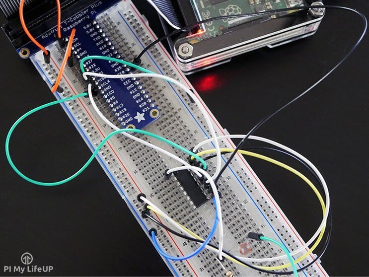
The circuit for connecting the MCP3008 to the Raspberry Pi looks quite involved, but it’s all about just connecting the wires up correctly.
The MCP3008 Pin Out Explanation
The MCP3008 is the chip that I will be using in this Raspberry Pi ADC tutorial. There is a lot of technical information on this chip, but I will just touch on the bare basics.
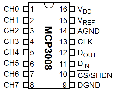
For anyone who is new to microchips, you will find that one end of the chip will have a notch in it. This notch represents the end where pin 1 is. It is usually the first pin on the left-hand side with the notch facing away from you (see diagram below). Pin one also sometimes has a little dot above it.
This particular chip makes use of the SPI (Serial Peripheral interface bus) which means it will only require four pins and is relatively easy to communicate to thanks to the SPIDev library for Python.
The CH0->CH7 pins (Pins 1-8) are the analog inputs for the MCP3008. On the other side, we have a whole range of different pins.
- DGND (Pin 9) is the digital ground pin for the chip.
- CS (Pin 10) is the chip select.
- DIN (Pin 11) is the data in from the Raspberry Pi itself.
- DOUT (pin 12) is the data out pin.
- CLK (Pin 13) is the clock pin.
- AGND (Pin 14) is the analog ground and obviously connects to ground.
- VREF (Pin 15) is the analog reference voltage. You can change this if you want to change the scale. You probably want to keep it the same so keep this as 3v3.
- VDD (Pin 16) is the positive power pin for the chip.
If you want more information on the chip, you can find the full datasheet at Adafruit.
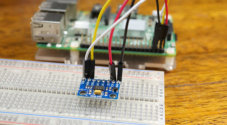
Assembling the Circuit
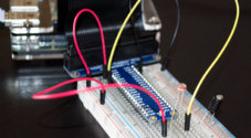
Putting the circuit together is pretty straightforward. The circuit is likely to look a bit messy since we’re going to have to use quite a few wires. You can clean this up later if you want to make it more of a permanent project.
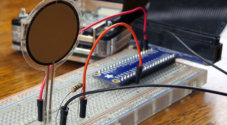
In this example, I have included an LDR to show how you can get the value of the LDR back to the Pi by using the analog to digital converter (ADC).
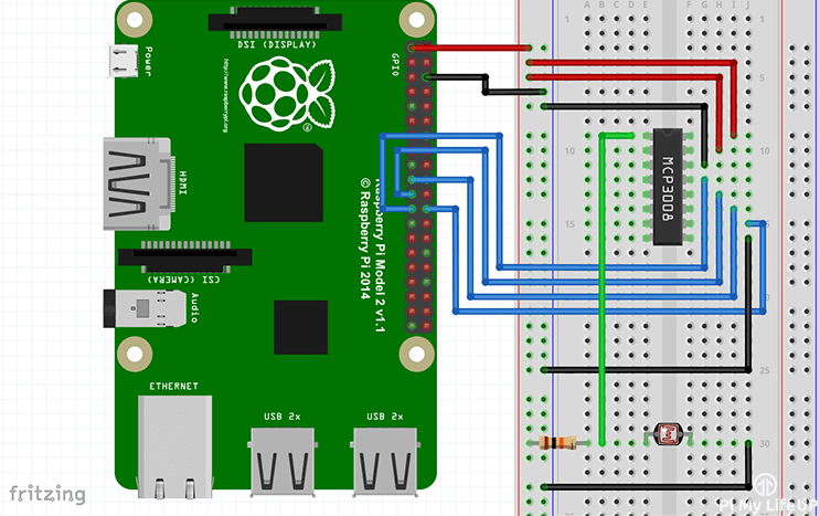
First, connect a 3v3 pin to the positive rail on the breadboard and a ground pin to the ground rail on the breadboard. Also, place the MCP3008 chip into the middle of the breadboard.
- VDD (Pin 16) wire this to 3.3V
- VREF (Pin 15) wire this to 3.3V
- AGND (Pin 14) wire this to ground
- CLK (Pin 13) wire this to GPIO11 (Pin 23/SCLK)
- DOUT (Pin 12) wire this to GPIO9 (Pin 21/MISO)
- DIN (Pin 11) wire this to GPIO10 (Pin 19/MOSI)
- CS (Pin 10) wire this to GPIO8 (Pin 24/CE0)
- DGND (Pin 9) wire this to GROUND
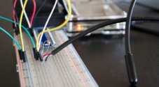
Once you have done that you will probably want to connect the LDR up to the MCP3008, this is easy to do.
First, place the LDR onto the breadboard. Next, have the 10k resistor go to one end of the LDR and the other end to the positive rail. Have a wire go from in between the LDR and the positive wire to pin 1 (CH0) of the MCP3008. Lastly, have a wire go from the other side of the LDR to the ground rail on the breadboard.
If you need further help on making the circuit, you can find a detailed diagram below. If you’re still having trouble, double check the chip connections, and also making sure all the pins are connected correctly.
Python Code for an LDR
The code for this is pretty simple but is also only handling just one input, the LDR. The code may be a little more complicated the more devices you add.
All the required packages for this tutorial should be installed by default on Raspberry Pi OS.
Our Python basics guide is excellent if you’re new to Python coding and wish to learn more. You should still be fine to complete this tutorial with little to no Python knowledge.
If you come across any issues, then check out my guide on the Raspberry GPIO pins. It goes through how to set them up and install the necessary software.
1. To quickly download the code straight onto your Pi just run the following line in the terminal. Alternatively, you can download it over at GitHub.
git clone https://github.com/pimylifeup/Pi-ADC-Example-CodeCopy2. You will need to change the directory to the directory that contains our script by running the following line.
cd ./Pi-ADC-Example-CodeCopy3. You can now launch it by running the following line.
sudo python adc-code.pyCopyYou can stop the script by pressing CTRL + C.
4. I will now just briefly explain the code. At the start of the code, we define the path of where Python is installed. After this, we import two packages that we will need.
- Time allows us to put the script to sleep (Add a delay).
- Spidev allows us to communicate with SPI devices, in this case, it is the MCP3008.
#!/usr/bin/python

import spidev
import timeCopy
Next, we define the variables and create our SPIdev object. We create two variables first being a delay in milliseconds. Alter this if you want there to be a more considerable amount of time between updates. Next is the channel our LDR is located on, this is channel 0/pin 1.
Finally, we create the SPIdev object. This object allows us to get the values we need from the device connected the SPI enabled pins.
#Define Variables
delay = 0.5
ldr_channel = 0

#Create SPI
spi = spidev.SpiDev()
spi.open(0, 0)Copy
Next, we have the readadc function in which we do a couple of things.
First, we check the parameter value to make sure it’s between 0 and 7, if not then return -1. If it is, we proceed to get the value from the channel specified and then return the value.
def readadc(adcnum):
    # read SPI data from the MCP3008, 8 channels in total
    if adcnum > 7 or adcnum < 0:
        return -1
    r = spi.xfer2([1, 8 + adcnum << 4, 0])
    data = ((r[1] & 3) << 8) + r[2]
    return dataCopy
Lastly, we have a while loop that continues until you force quit it by pressing CTRL + c. The first thing we do is call the readadc function with the ldr_channel variable as the parameter.
Once we get the value, back we simply print it. The %d refers to a decimal value; we then have our variable after the print statement. You can print multiple values per line by doing something like this. print '%s %d' % (name, number)
After we have printed the data, we delay the script for whatever the delay time is set to. By default, it is set for half a second.
while True:
    ldr_value = readadc(ldr_channel)
    print "---------------------------------------"
    print("LDR Value: ".ldr_value)
    time.sleep(delay)Copy
I hope this has helped you understand the code a little. As I mentioned above, you can download the full script over at the project’s GitHub.
Conclusion
You can follow this same process for any analog device. I will cover sensors or devices that are analog in the near future. It may include things such as the tmp36 temperature sensor.
I hope this tutorial has helped with setting up a Raspberry Pi ADC. If you come across any issues, have feedback or notice a mistake, please feel free to leave a comment below.
I always get “LDR Value: 1023”. Not sure what I did wrong, I closely followed the tutorial. Any small hints? No need to write an essay, just a small hint please. Anyone?
Thomas,
I had the same issue. Apparently, the voltage being fed to the ADC is 3.3V (by connecting it to Vcc according to the tutorial.) which is the max voltage and so you get the LDR value as 1023 which is the maximum. You didn’t do anything wrong. I feel we are missing out some point on using the photo resister (how the value will be fluctuating) that would alter LDR value but I’m not sure how to fix it.
Hello,
Thank you for the tutorial. I learned alot. After setting up though when i run the code, i get ldr value = 0. Which tells me its not really gathering any data. How can i best troubleshoot for this?
This is a very clear and helpful tutorial which complement the You Tube video.
The pin out diagram and the wiring diagram are a great help too.
The code works perfectly as well.
Many thanks Gus.
Hi there! Congratulations on the tutorial, I found it very helpful. I see that you connect the ADC to 4 of the GPIOs in the PI (apart from ground and 5v), these are pins number 8,9,10 and 11. Is it possible to connect several MCP3008 to the same Raspberri so that we can read more analog inputs and connect the new MCP3008 to different GPIO’s?
Obviously you can attach up to two ADC chips using GPIO8 and GPIO7 (CE0 and CE1). Attach them to CS pins of your ADC chips. In this way you’ll get 16 channels. As I suppose, you can have even more, but you’ll can’t use standard Python library then. For example, you could attach a binary demultiplexer to some GPIO outputs of your choice and switch up to 2^n chips, where n is the number of GPIO pins used. But Py library doesn’t support it, so you’ll need to use spi.open(0,0) and switch ADC chips by setting/resetting GPIO pins. I never tried it, but I don’t see a reason why this way couldn’t work.
First, great tutorial!
I understand that the raspberry pi can only read voltages up to 3.3V. However, since we’re using the chip to convert the voltage, does the voltage coming into the ADC still need to be between 0 and 3.3V??
I’m assuming is that the ADC is “receiving the voltage” not the raspberry pi. Am I incorrect with this assumption?
That’s correct. An ADC only outputs binary numbers so you are safe to supply the ADC with 5V. You will just need an external source to provide the voltage as Raspberry Pi only has the capability to provide 3.3V.
Dear Sir
Will you please provide tutorial for interfacing
Mcp 3208 adc
BMW
Hi Balkrishna,
I will add it onto my list of things to look into!
Gus,
I noticed you hook the ADC to the 3.3V rail. If I have a sensor that outputs 0-3.6V can I just connect the MCP3008 to the 5V rail instead? Also the values that the pi was displaying in the video from the photo resistor was something like 613. What exactly is that value?
Thanks,
PJ
Thanks for a great tutorial.
I want to do several projects using various analog sensors – temperature, vibration, etc. I’m sure your tutorial on using the ADC converter will be a big help. But I have 2 questions:
1 – You use the MCP3008. I’ve seen many other “similar” chips on e-bay – for example: PCF8591T or ADC0809CCN. Do you know if they could be substituted for the chip you use?
2 – I’ve seen several sensor kits advertised, but although many of them mention the Raspberry Pi, they don’t seem to include Python code – only C++ code for the Arduino. I’m including a link to one such kit. Do you think the sensors in this kit would work with the code you’ve demonstrated?
In the video, you skipped over the line
spi.open(0, 0)
with no explanation. Obviously, it starts things happening but what are the parameters (0, 0)?
Hi Paul,
Sorry about that!
spi.open(bus, device)
Bus is the SPI bus we want to use. Since the Pi only has 1 this is 0.
Device is the chip select/GPIO Pin we want to use. CE0 or CE1 (0 or 1)
I hope that answers your question