In this tutorial, we’re building a Raspberry Pi motion sensor that makes use of a PIR sensor (Passive Infrared Sensor).
A PIR sensor is a simple but excellent device for detecting when motion has occurred. In older style security systems these sensors were used a lot. However, most modern systems use video. I explain a bit more about the sensor further down this page.
To make this project a little more interesting, we will also be using a piezo speaker whenever motion is detected. Both these devices will need to be hooked up to the GPIO pins to work.
If you’re unfamiliar with electronics, then this tutorial is the perfect way to introduce yourself to different parts and circuits. I highly recommend investing in a breadboard as it will make building circuits a lot easier.
Equipment
In order to do this project, you will need some equipment this includes a Raspberry Pi PIR sensor and a piezo speaker.
Recommended
- Raspberry Pi Amazon
- Micro SD Card Amazon
- PIR Sensor Amazon
- Piezo Speaker Amazon
- 100 ohm resistor Amazon
Optional
- Ethernet Cable Amazon or Wi-Fi Amazon
- GPIO Breakout Kit Amazon
- Breadboard Amazon
- Breadboard Wire Amazon
While the breakout board, breadboard, and the wire are optional, I do highly recommend using these as they will make your life a lot easier. Also, be sure to check out some of the best Raspberry Pi cases you’re able to get.
Video
If you would like to see a video on how to do this Raspberry Pi motion sensor, then be sure to check out the video I have prepared below.
Please be sure to follow us on social media or sign up to our mailing list if you like our content and would love to stay up to date on all the latest projects.
Raspberry Pi PIR Sensor Hardware Setup
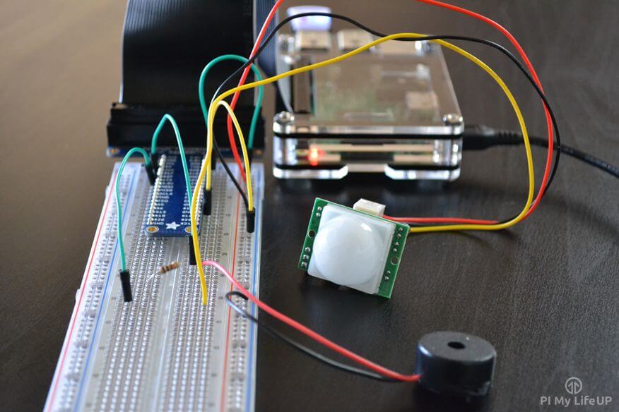
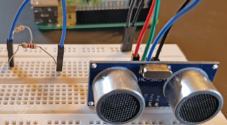
We will be putting together a simple circuit that makes use of a PIR sensor and also a piezo speaker.
A PIR sensor is most commonly seen in security systems to detect movement before sending the alarm off. They detect motion whenever there is a change of infrared temperature in their field of view.
Most PIR sensors have some adjustable screws on them that will allow you to adjust both the time and sensitivity of them. The time will allow you to set a delay before it goes off (Send a high signal). (About two to four seconds). The sensitivity is how much movement needs to occur before it goes off.
The piezo buzzer is a simple speaker that outputs a sound whenever a current is traveling through it. In this circuit, the buzzer will give a loud beep whenever the motion detector circuit is triggered.
A breadboard isn’t necessarily a requirement for this project, but I would highly recommend using one. A breadboard makes prototyping and building circuitry a lot easier.
You don’t have to use a breadboard like I am you can simply hook these straight up to the Raspberry Pi.
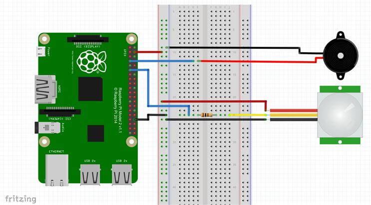
To construct the circuit simply do the following.
1. Run a ground pin to the ground rail on the breadboard.
2. Run a 5v pin to the positive rail on the breadboard.
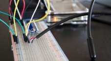
3. Connect the piezo buzzer to pin 7 (Red wire) and the ground rail (Black wire).
4. Run a wire from pin 11 to the breadboard. Place a 100-ohm resistor at the end of the wire. Then connect this up to the yellow wire of the PIR sensor.
5. Now for the PIR sensor run the red wire to the 5v line and the black wire to the ground rail on the breadboard.
Raspberry Pi Motion Sensor Software Setup
To bring our Raspberry Pi Motion sensor circuit to life, we will need to do a little programming. This programming is relatively easy and much like our introductory post to the Raspberry Pi GPIO pins is an excellent way to learn the basics of Python.
1. If you do not feel like typing out the full script, you can download it using wget. Alternatively, you can also download it directly from my GitHub page.
sudo wget https://github.com/pimylifeup/motion_sensor/archive/master.zipCopy2. Now extract the archive using unzip.
unzip master.zipCopy3. Next, change directory, to the script folder.
cd ./motion_sensor-masterCopy4. Lastly, on the Pi enter the following command to open the Python script and load it in the nano text editor.
sudo nano motion_sensor.pyCopyCode Explanation
I will briefly explain what each part of the code does.
Firstly, we import the GPIO and time Python packages as we will need these to be able to interact with the GPIO pins and also pause our script.
We set three variables, the first two are references to our pins, and thus I have named appropriately. The current state variable is where we will store our sensor state. If this is 0, then it is off, or 1 means it has been activated.
For this tutorial, we will set our GPIO mode to reference the physical numbering of the pins rather than the actual numbering. This numbering is a little easier to understand as all the pins are numbered in order.
We also set up our GPIO pins to be either outputs or inputs. For example, we want to detect motion so our PIR sensor will be input. On the other hand, our piezo buzzer is going to need to act as an output.
import RPi.GPIO as GPIO
import time

pir_sensor = 11
piezo = 7

GPIO.setmode(GPIO.BOARD)

GPIO.setup(piezo,GPIO.OUT)

GPIO.setup(pir_sensor, GPIO.IN)

current_state = 0Copy
In this next part, we have an infinite while loop. This loop means it will never exit because it is always true. (You can still cancel the script by press ctrl + c in the terminal).
We begin by putting the script to sleep for 0.1 seconds. After this, we get the current state of the sensor, and if it is 1 (e.g. detected motion), then we run the code inside the if statement. If it isn’t 1, then we continue to loop continually checking the sensor.
The code in the if statement sends the piezo buzzer to high that should emit a noise. The script will do this for a second then turn the buzzer off. After this, it will wait for another 5 seconds before exiting the if statement and then rechecking the Raspberry Pi PIR sensor.
We have also nested out code within a try, except, finally block. We have added this because we will need to use the keyboard to stop the script. It is also very important that we run GPIO.cleanup() to ensure our script cleans up nicely. The try, except, finally code allows us to do this.
try:
    while True:
        time.sleep(0.1)
        current_state = GPIO.input(pir_sensor)
        if current_state == 1:
            print("GPIO pin %s is %s" % (pir_sensor, current_state))
            GPIO.output(piezo,True)
            time.sleep(1)
            GPIO.output(piezo,False)
            time.sleep(5)
except KeyboardInterrupt:
    pass
finally:
    GPIO.cleanup()Copy
Running the Script
Once you have finished working in the script it’s now time to turn it on and test it out. To do this, enter the following command.
sudo python motion_sensor.pyCopyIf you move in front of the Raspberry Pi PIR sensor, then it should turn the piezo buzzer on and emit a noise.
If it doesn’t then is likely you have hooked up wires to the wrong pins, or there is an error in the code. If it is a code error, you will most likely see an error in the terminal of the Raspberry Pi.
Conclusion
This tutorial is pretty basic and only the beginning of the many applications you can use the PIR sensor. You can get it trigger all sorts of things from something as simple as a counter (counts as people/cars/things go past it), a Raspberry Pi camera, activate a different script and lots more.
I hope you enjoy this Raspberry Pi motion sensor tutorial and have been able to build a cool circuit and bring it to life with code. If you have any feedback, thoughts, troubles or anything else, then feel free to drop us a comment below.


hi Gus,
I’ve been playing with this sensor all day and never could get it to work. Signal was always high. It was driving me nuts. I found your site (and subscribed). I noticed you had a 100 ohm resistor. I added that and it is stable.
So my question is why does the resistor resolve the problem and how did you figure that out?
Thanks
Hi Boyd,
Really glad to hear that this tutorial helped sort out the issues you were running in to. Dealing with issues like that can get incredibly frustrating.
The resistor is used within this circuit to create a “pull down”. What this does is give us a consistent reading of 0v reading (Logical low) when there is no signal being output from the sensor.
Hopefully that answers your question, and if you need more of an explanation, I’ll try my best.
Kind Regards,
Emmet
Thanks. After playing with it more, it stopped working and stays at high. I even upped register to 330 ohms with no improvement.
I tried a second sensor with same results. Also moved to different gpio pins with no change.
If i remove the resistor the circuit goes open and everything stops. Very bizarre.
Thanks Emmet.
I played with it some more and PIR sensor stopped working reliably and signal stayed high. I even upped the ohms and no change.
Have you found those sensors to be flaky?
Hi Boyd,
I haven’t experienced any issues with my limited usage of the PIR sensors. I’m not entirely sure what to suggest here besides maybe moving up to a 10kohm resisitor and see if that helps at all.
Kind regards,
Emmet
This was fun… I really enjoyed having set up, code and execute everything perfectly! 🙂
Hello, thanks so much for this, I was able to get everything setup as instructed and it works perfectly! I’m trying to incorporate this project into some Halloween decorations, so that when trick-or-treaters come, it detects them walking by and activates some spiders in my yard. Originally they were activated by a microphone in the plastic body (unfortunately it’s VERY unreliable), in years past I triggered them manually using a button, and I thought this would be a nice upgrade. I figured I could just run the cut microphone wires to the breadboard in place of the piezo speaker, but the spider just runs constantly even without the PIR being triggered. I’m probably missing something obvious, if anyone can steer me in the right direction I’d be hugely grateful. Thanks!
Step 3: Connect the piezo buzzer to pin 7 (Red wire) and the negative rail (Black wire).
There is no negative rail set up in steps 1 or 2.
Please explain
Thanks in advance
Hi Linda,
Thank you for pointing that out. It should read ground rail. I have fixed it now.
Very Interesting. Can this setup be used to measure distances using a PIR and a mirror?
While technically it is possible to use a PIR sensor to measure distance you’re better off using an ultrasonic sensor or something similar.
Gus – what did you do about an enclosure for the breadboard and motion sensor? Any good ideas? I plan to use this with a battery pack to make it portable.
Thanks again – Jim
Hi Jim,
Unfortunately, I never ended up building an enclosure. There are lots of good ideas on 3D print websites such as Thingiverse that’s worth checking out.
Thanks for getting me started. Your project worked great! I substituted a red LED for the speaker and used this to also trigger a camera for a series of 3 snaps.
Great job –
Can a separate python script be ran from this by replacing
GPIO.output(piezo,True)
? I’d like to set this up and hide it, connected via wifi, running off of a battery, and SSH’d into from my main PC so if I could find a way to have this notify me somehow that’d be perfect.
Yes, in theory, that should work.
Very interesting tutorial. It would be fantastic if. you can teach us how to use a PiCamera instead of a Buzzer ^_^
This is great project! I changed the code for buzzer to a controllable time range and tone.
I need to interface vibration sensor(sw 420) along with pir motion sensor. Is this possible?. i am getting output for pir detection, but have to interface both. can anyone help with code.thanks in advance 🙂
Here is a little modification of the code I did that logs the unix timestamp when a movement is detected to a database . I removed the piezo code because I did not connect piezo speaker to my pi.
You can then convert this value to human time-stamp in php for example:
while($row2 = mysql_fetch_array($retval2, MYSQL_ASSOC)) { $humantime = $row2['Timestamp']; $finaltime = date("Y-m-d\ T H:i:s\ ", $humantime); echo "last detected movement was on {$finaltime} ";how can you do this project but replace the buzzer with a led?
Hi,
You really just have to physically replace the buzzer with a LED, that’s what I did and it flashes the LED instead of making a sound. No changes needed otherwise 😉
Hello there! I am interested in working on a project similar to this one but i need to add a temperature sensor to this circuit,
can you please suggest what i should do and what code i have to adjust! thank you for your time!
Thanks for this tutorial. Anyone else able to get the motion sensor working? I’ve got it hooked up exactly as the video, but I only get GPIO 11 is 1, repeating over and over, and either the sensor doesn’t pick up movement, or the signal is not being processing properly. Any ideas on how I can troubleshoot?
Hi Citizenchan,
On the sensor itself there should be two screws try adjusting these until the sensor is no longer sending pin 11 high all the time. I found it took quite a bit of tinkering to get the perfect level.
In the script you can also try changing the setup line for the input pin to the following.
GPIO.setup(pir_sensor, GPIO.IN, GPIO.PUD_DOWN)Excuse me, I’m working on a project where I have to use multiple PIR sensor. The idea is to use two for each spot to show when is occupy. Also, I have to create an error message if only one sensor is activate. Any suggestions on how can I decelerate multiple PIR sensors? Or create the error message?
Hello,
I’m trying to replicate the same project with a passive PIR Motion Sensor and a 30V(P-P) Max peizo transducer from radioshaq, but I’m not getting the same result. I can hear the piezo transducer (buzzer) every 5 seconds without me activating the motion sensor.
Do you guys see what’s the problem?
Thanks,
Christian
Hi Christian,
There are a couple of things you can do to try and fix this. First try adjusting the two adjustable screws that should be located on the PIR sensor. I had to turn the sensitivity down quite a bit.
The other option is adding pud_down to to our GPIO.setup line for the sensor. Eg.
GPIO.setup(pir_sensor, GPIO.IN, GPIO.PUD_DOWN)I hope this helps.
Thank you Gus. It’s working now
Hi If I wanted to set up a camera to snap shots when the motion detector picks up motion and have it emailed or stored preferably on a cloud what will the coding look like?
Actually, mostly the same… Just replace the line GPIO.output(piezo,True) by the code to take a picture and send it wherever you want (you’re gonna get 1 picture per second, you may want to alter the delay too…)
Thank you for the reply. I will try it out.
Hello Gus;
I see your project for motion sensor; it’s very good, thank you for sending me your tutorials; I built a raspberry webcam server, it’s functional very good, so I have Raspberry pi2 and I’m interested to make surveillance with webcam and if there is a motion detection like you did, the webcam will take a picture and the raspberry pi2 will send an notification e-mail with picture and a small streaming to my email address in Google for example. I saw some examples that send e-mail but not a picture.
Would you like to help me to build this project? Or would you like to make it in your future tutorials.
Thank you very much.