In this guide, we will be exploring a very crucial and fundamental element in electronic circuits, and that is voltage dividers.

A voltage divider is a somewhat basic passive circuit that plays a very crucial role. In basic terms, a voltage divider transforms a large voltage down into a smaller one.
A basic voltage divider circuit consists of two resistors wired in series that produces an output voltage that is just a fraction of its input voltage.
The input voltage is applied across the two resistors with your desired output voltage coming from the connection between the two resistors. The second resistor is typically connected to ground.
Basic Voltage Divider Circuit
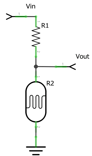
Below are some examples of how you could see a voltage divider circuit setup or drawn.
All voltage divider circuits should look fairly similar. The circuits should consist of two resistors. One resistor should be connected to ground, the other to a source voltage and a wire coming from in between the pair with the output voltage.
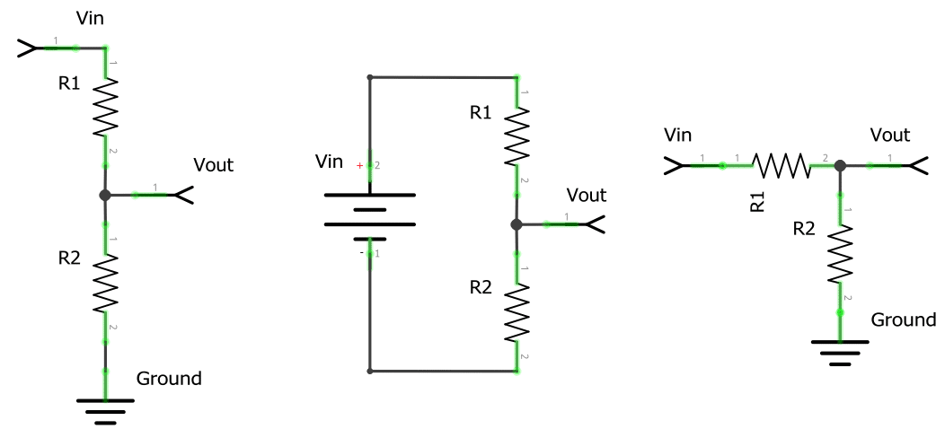
As you can see in a basic setup of the voltage divider circuit the resistor that is closest to the input voltage (Vin) will usually be referred to as R1. The resistor that is closest to the ground connection is typically referred to as R2.
The voltage drop that is caused by the input voltage going through the resistor pair (R1 and R2) is referred to as Vout.
The resulting voltage drop is what we will be referring to as our divided voltage. This divided voltage is a fraction of the original input voltage (Vin).
We use R1, R2, Vin, and Vout to name elements of the circuit as they are crucial to understanding the values you will need for the voltage divider equation.
The Voltage Divider Formula
The voltage divider equation assumes that you know three of the values utilized in the circuit.
The values that you will need to know to make use of the equation are the following three.
You will need to know both the resistor values (R1 and R2) and also the input voltage (Vin).
Utilizing these three values in the equation below will allow us to calculate the output voltage of a voltage divider circuit.
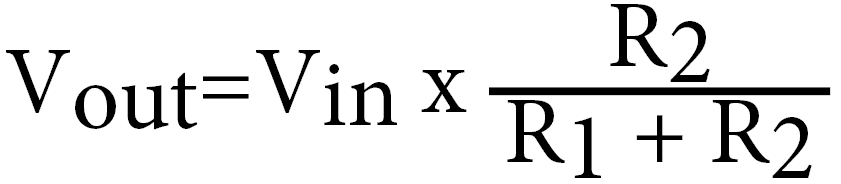
We will now go over the variables used in the voltage divider equation one final time so that you will have a solid understanding of each variable.
- Vin is the input voltage measured in volts (V)
- R1 is resistance of the 1st resistor in the voltage divider, measured in Ohms Ω
- R2 is resistance of the 2nd resistor in the voltage divider, measured in Ohms Ω
- Vout is the output voltage measured in volts (V)
Voltage Divider Calculator
If you want to quickly calculate the output voltage generated by your voltage divider circuit then you can make use of our handy calculator.
All you need to do is enter the values for your two resistors and the input voltage, the calculator will automatically work out the corresponding output voltage.
Voltage Divider Formula Examples
For our first example of utilizing the Voltage Divider formula we are going to utilize the following values:
- Vin as 5v,
- R1 as a 220Ω resistor,
- and R2 as a 680Ω resistor.
Now if we plug these values into our voltage divider equation, we should end up with something like what we have displayed below.
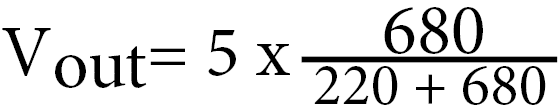
To begin with, we will first plus the R1 and the R2 resistor values together. So in our example above, this will end up being 220 + 680, which is equal to 900.
We will replace 220 + 680 in our formula with our result, so that we end up with the following equation.
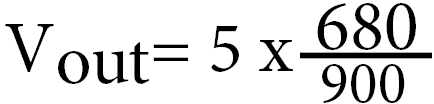
Now that we have done the simple addition we can finally calculate the division part of the voltage divider equation.
Just divide your R2 value with your calculated R1 + R2 value. In our example, this will be 680 divided by 900.
Using a calculator this will give us 0.7555555555555556, but for simplicity we will round this to 2 decimal places, meaning the number will become 0.76.
Replace the division part of your formula with the value you have gotten, your equation should now look like what we have below.

Finally, we can just multiply the Vin with our calculated resistor division amount. In our case simply multiply 5 by 0.76.
The result of this multiplication will give you your Vout amount. In our case this result was 3.8 Volts.
The Formula Simplification
There are a few simplifications we can make to the voltage divider equation. For this guide, however, we will only walk you through the one below.
Using simplifications you can make it easier to evaluate a voltage divider circuit quickly.
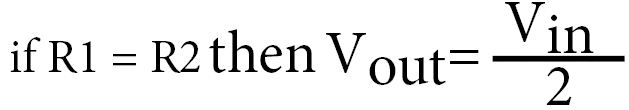
This simplification says that if the value of the R1 resistor and the R2 resistor are the same, then the voltage out is equal to half the input voltage.
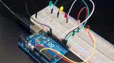
Voltage Divider Applications
Voltage dividers have many applications in electronic circuitry and are a core component of many electronic circuits.
Below we will show you some of the few applications of the voltage divider circuit.
Potentiometers
A potentiometer is one of the most well-used pieces of electronic circuitry and is featured as a core component in a large array of different products.
Some examples of the sort of devices that a potentiometer is used in are the following:
- Measuring the position on a joystick
- Creating a reference voltage
- Controlling the audio level in speakers
- Among many other things
A potentiometer is a variable resistor that acts just like adjustable voltage dividers.
Inside the pot is a single resistor that is separated by a wiper. This wiper is what you move that adjusts the ratio between the two halves of the resistor.
Outside of the pot, you will find three pins, the pins on either side are the connection between each end of the resistor, you could consider these as being R1 and R2.
The pin in the middle is what is connected to the wiper. This theoretically is like the Vout in a voltage divider circuit.
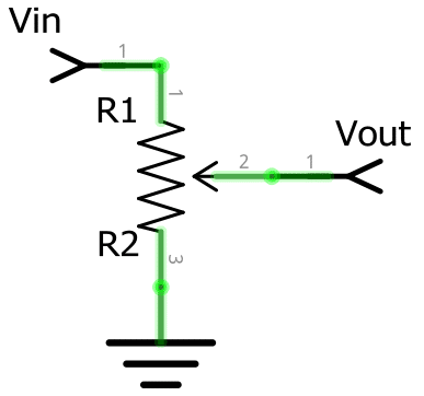
To wire a potentiometer so it acts like an adjustable voltage divider you will need to connect one side to your input voltage (Vin) and the other side to your ground.
With both of the two outside pins wired correctly, the middle pin will then act as your voltage dividers output (Vout).
Turning the pot in one direction will make the voltage go towards zero, setting it to the other side will make the voltage approach the input voltage.
Turning the pot to the middle position will effectively mean the output voltage will be half the input voltage.
Level Shifter
A level shifter is an important concept to understand when dealing with digital electronics. They can also be called a “logic-level shifter” or “voltage level translation” circuit.
Level shifters are used to shift the voltage from one level to another. This is often used to allow compatibility between ICs that have different voltage requirements.
Some of the more complicated sensors that utilize interfaces such as UART, SPI, or I2C to transmit their readings often deal with different voltage levels.
One example of potential usage of this is when dealing with a microcontroller board such as the Raspberry Pi.
The Raspberry Pi is an interesting example of where a level shifter is handy. Even though the Raspberry Pi provides both 5v and 3.3v power outputs, its GPIO pins are only built to handle a 3.3v input.
Utilizing a voltage divider within a circuit will allow us to step down the voltage from 5v down to 3.3v for the input pin.
Below we will run through an example of using a voltage divider circuit with the Raspberry Pi to level shift the output of a sensor from 5v do to 3.3v.
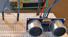
Example of Level Shifting
For example, in our distance sensor tutorial, we utilize the HC-SR04 ultrasonic sensor.
This sensor utilizes a 5v power input, meaning we need to step down the output on the Echo pin from 5v to 3.3v before it reaches the GPIO Pins.
We can calculate the resistors we need by choosing an initial resistor value. Resistors between 1kΩ–10kΩ work best for dropping the voltage from 5v to 3.3v.
For our example, we will utilize a 1kΩ resistor. To work out the second resistor that we need to use we will use yet another re-arranged version of the voltage divider equation.
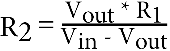
To calculate the R2 value we need to know the Vin, the Vout and the value of our R1 resistor that we plan on using.
With those 3 values handy we can utilize the following equation.
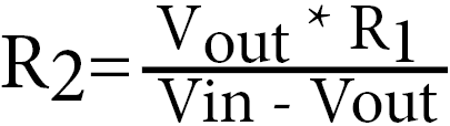
Filling that equation in with our known values, we can use it to calculate the value of the resistor that we need to drop the voltage from 5v to 3.3v.
With both our input and output values and our R1 resistor of 1kΩ you should end up with the following equation.
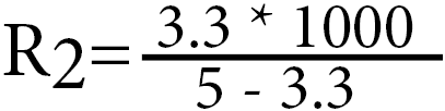
First, you should calculate both halves of the division, if you multiply the Vout (3.3) by the R1 (1000) value you should get 3300.
Now we also need to do the bottom half, subtracting the Vout from the Vin, in this example that is 5 – 3.3 which is equal to 1.7.
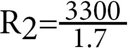
Finally, divide both values to get your resistance value, in our example, this is 3300 divided by 1.7.
Putting this into a calculator we get a big long number, but we will simplify this to the closest 2 decimals.
With this value, we can deduce that a 2kΩ resistor should be more than enough to lower the 5v voltage down to 3.3v.
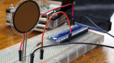
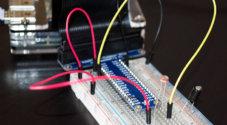
Reading Resistive Sensors
One thing you may notice is that many sensors in the real world are just simple resistive devices designed to react to certain elements.
For example, an LDR (Light Dependent Resistor) Sensor like that we use in our light sensor tutorial works by producing a resistance that is proportional to the amount of like that is touching it.
There are also many other sensors that are effectively just fancy resistors such as thermistors, flex sensors, and force-sensitive resistors.
Sadly though unlike voltage (Coupled with an analog-to-digital converter), resistance is not as easy to measure for computers such as the Raspberry Pi.
However we can make it easier by rejigging the circuit to be a voltage divider. This is simple as adding a resistor so the circuit is much more like the circuits we showed earlier in this guide.
That way we can utilize the voltage provided to us from the voltage divider to calculate the current light level.
Adding a resistor of a value you know, such as a 1k ohm resistor you can then work out the resistance of the LDR at different light levels by re-arranging the equation used earlier.
All we need to know, is the Vin, the Vout, and the R1 resistor value.
Using the above equation you can quickly calculate the resistance of the LDR at its darkest level of light and its brightest.
This would give us an idea of its highest and lowest resistance.
When you have both of these resistance values, you can work out a resistor value that sits in between, this will give you the largest resolution for calculating the current light through an analog-to-digital converter.
For example, a photocell’s resistance can vary between 1kΩ in the light and approximately 10kΩ in the dark.
So by utilizing a resistor that has a value somewhere in the middle, such as a 5.1kΩ resistor, we can get the widest range out of our LDR.
I hope that this guide has helped you understand what a voltage divider is and how you can use it in circuitry as well as calculate its resulting voltage.
If you think we have missed something or have got something wrong then be sure to let us know in the comment section below. We’re also open to any other feedback that you might have.


Just subscribed. Very impressive! Just what I was needing. Keep up the good work!
James Davis, P.E.