In this tutorial, we will show you how you can easily set your Raspberry Pi up to read the temperature from the DS18B20 sensor.
Like most of our sensor tutorials, the temperature sensor we are using with our Raspberry Pi will be relatively simple to use.
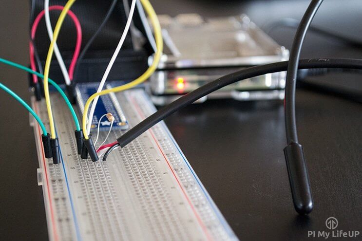
In this guide, we will use a DS18B20 waterproof sensor, which can provide temperature readings over a one-wire interface. Even better, it is waterproof, making it perfect for use in a wet environment.
Thanks to the DS18B20 sensor, getting temperature readings on your Raspberry Pi is pretty straightforward. Connecting the sensor requires a few simple connections, and reading the live data is easy.
There are many other temperature sensors you can use with your Raspberry Pi, but in this tutorial, we will focus on the DS18B20.
You will find the DS18B20 temperature sensor handy in many situations, especially for monitoring surface and liquid temperatures.


Equipment
The equipment that you will need for this Raspberry Pi temperature sensor is listed below.
Keep in mind the breadboard, and the breadboard wire is optional, but I highly recommend investing in these, as they may make working with circuitry a lot easier.
Recommended
- Raspberry Pi Amazon
- Micro SD Card Amazon
- DS18B20 Temperature Sensor Amazon
- 4.7k ohm Resistor Amazon
- GPIO breakout kit Amazon
- Breadboard Amazon
- Breadboard Wire Amazon
Optional
Video
If you want to see how to put together the circuit and a rundown of the code, then be sure to check out my video below.
I go through everything there is to know about this cool little circuit in the video. You can also find the full written tutorial right under the video.
Building the Raspberry Pi DS18B20 Circuit
The circuit that we will need to build is pretty straightforward as we only need a resistor and the temperature sensor.
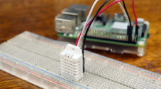
The sensor I am using in this tutorial is a waterproof version of the DS18B20. It simply looks like a very long cord with a thick part on one end. If you have a plain version without wiring or waterproofing, it looks exactly like a transistor.
This sensor is pretty accurate, being within 0.05°C of the actual temperature. It can handle temperatures of up to 125°C (260°F), but it’s recommended you keep it below 100°C (210°F). This device also has an onboard analog-to-digital converter, so we’re able to easily hook it up to a digital GPIO pin on the Pi.
Keep in mind that not all temperature sensors are the same. Something like the TMP36 will not simply replace the DS18B20 in this tutorial.
The TMP36 is an analogue device, making it slightly harder to integrate with the Pi. The TMP36 has the same problem we had with the light sensor, because the Raspberry Pi doesn’t have any analogue pins.
Putting this circuit together is super simple. I will quickly go through some basic instructions below. If you’re having trouble following them, then please refer to the video or diagram.
If you need more information on the GPIO pins, then be sure to check out my guide to getting started with the Raspberry Pi GPIO pins.
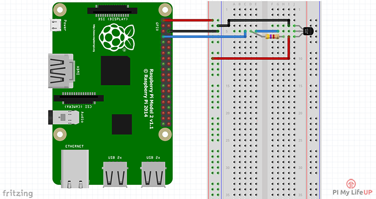
1. First, connect the 3v3 pin from the Pi to the positive rail and a ground pin to the ground rail on the breadboard.
2. Now place the DS18B20 sensor onto the breadboard.
3. Place a 4.7k resistor between the positive lead and the output lead of the sensor.
4. Place a wire from the positive lead to the positive 3v3 rail.
5. Place a wire from the output lead back to pin #4 (Pin #7 if using physical numbering) of the Raspberry Pi.
6. Place a wire from the ground lead to the ground rail.
Once done, your circuit should look similar to the diagram below. Keep in mind some versions of the temperature sensor may have more wires than just three. Refer to the datasheet for more information for each of the wires.
The Raspberry Pi Temperature Sensor Code
The code for setting up the temperature sensor is a little more complicated than the circuit itself. This complexity is just because of how we need to handle the data from the sensor on our Raspberry Pi.
Since we are using Python, it will be worth learning some basics of the language. If you are interested in learning, we recommend checking out our Python beginners’ guide.
Over this next section, you will be learning how to enable OneWire support that is required to talk with the DS18B20 sensor, as well as how to use Python to talk with the sensor.
Enabling OneWire Support on your Raspberry Pi
1. Before we can begin writing our Python script so our Raspberry Pi can read data from the temperature sensor, we must enable OneWire support.
To add support for OneWire, we first need to open the boot config file and make some changes. You can open this file by running the following command. I like to use the nano text editor.
sudo nano /boot/firmware/config.txtCopy2. Now, to the bottom of this file, you will want to add the following line.
This line enables the OneWire support on your Raspberry Pi and is what will enable it to read in data from the temperature sensor you wired in earlier.
By default, OneWire support on the Pi will utilize GPIO pin 4.
dtoverlay=w1-gpioCopy3. After making this change, you can save and quit by pressing CTRL + X and then Y.
4. Despite making this change, OneWire support isn’t yet enabled. For this change to take effect, we must restart our Raspberry Pi.
Restarting your Pi from within the terminal is as simple as using the command below.
sudo rebootCopyVerifying OneWire is Enabled
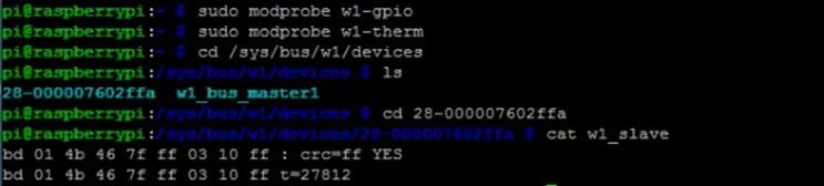
5. Once your Raspberry Pi finishes restarting, we can verify that it can see the attached temperature sensor. To achieve this, we will utilize the ls command to list out the contents of the “/sys/bus/w1/devices” directory.
Each directory listed by this command is a device connected to the OneWire interface on your Pi.
ls /sys/bus/w1/devicesCopy7. For example, after running the command above, we saw a directory named “28-000007602ffa“. To get an idea of the sort of data that is coming in from the sensor, let us start by changing into that directory.
The ending folder name is likely different for you, so be sure to swap this out with the folder you retrieved from the previous command. If you have multiple sensors, you would likely see multiple folders.
cd /sys/bus/w1/devices/28-000007602ffaCopy8. Once you are in the directory, you can utilize the cat command to get your Raspberry Pi to read data from your temperature sensor.
cat w1_slaveCopy9. This command should output data but as you will notice it is not very user-friendly.
The first line should have a YES or NO at the end of it. If it is YES, then a second line with the temperature should appear. This line will look similar to something like t=12323, and you will need to do a bit of math to make this a usable temperature that we can understand easily. For example, Celsius you simply divide by 1000.
Writing Python to Talk with your Temperature Sensor using your Raspberry Pi
10. Now that we are certain everything is working and that your Raspberry Pi can communicate with your temperature sensor, we can move on to writing some Python that will make use of this data.
Before we begin writing this code, start by ensuring you are in your home directory by using the cd command followed by the tilde symbol.
cd ~Copy11. With us now in the right place, we will use the Nano text editor to begin writing a new Python script. We will be calling this script “temperature_sensor.py“.
The code we are using within this script was sourced from the tutorial over at Adafruit. We will briefly explain each part of the code so you get a rough idea of what is going on. If you don’t want the explanation, just skip to step 12.
nano temperature_sensor.pyCopya. To begin the Python script, we import three packages: OS, Glob, and time.
Next, we run the modprobe commands to ensure that OneWire is enabled and that our Pi can communicate with the temperature sensor.
After this, we declare three different variables that will point to the location of our sensor data. You shouldn’t have to change any of these.
import os
import glob
import time

os.system('modprobe w1-gpio')
os.system('modprobe w1-therm')

base_dir = '/sys/bus/w1/devices/'
device_folder = glob.glob(base_dir + '28*')[0]
device_file = device_folder + '/w1_slave'Copy
b. We then declare a new Python function called “read_temp_raw“. This function is simple and is here to read the raw data the sensor is returning.
Once the data has been read in, we return it so that we can process it into actual usable temperature data.
def read_temp_raw():
    f = open(device_file, 'r')
    lines = f.readlines()
    f.close()
    return linesCopy
c. Up next, we define a new function called “read_temp” that we will use to process the data from the “read_temp_raw ” function.
We first make sure that the first line contains YES. This means there will be a line with a temperature in it.
If there is a temperature, we then find the line starting with “t=” by using “lines[1].find('t=')“. “lines[1]” means we’re looking at the 2nd element in the array, in this case, the 2nd line.
Once we have the line, we get all the numbers that are after the “t=” and this is done at “lines[1][equals_pos+2:]“. “equals_pos “is the start position of the temperature (t), and we add 2 to the position, so we only get the actual temperature numbers.
We then convert the number into both Celsius and Fahrenheit temperatures. We return both of these to the code that called this function. This function is the print located in the while loop.
def read_temp():
    lines = read_temp_raw()
    while lines[0].strip()[-3:] != 'YES':
        time.sleep(0.2)
        lines = read_temp_raw()
    equals_pos = lines[1].find('t=')
    if equals_pos != -1:
        temp_string = lines[1][equals_pos+2:]
        temp_c = float(temp_string) / 1000.0
        temp_f = temp_c * 9.0 / 5.0 + 32.0
        return temp_c, temp_fCopy
d. The while loop we are placing at the end of our script is always “true” so it will run forever until the program is interrupted by an error or by the user cancelling the script.
This while loop simply calls the “read_temp()” function and prints the result to the command line. The script is then put to sleep for 1 second every time it has read the sensor.
while True:
	print(read_temp())
	time.sleep(1)Copy
12. If you have entered all of the Python correctly, the code should end up looking like what we have shown below.
This bit of Python is super simple and is what will enable your Raspberry Pi to read in the temperature data from your DS18B20 sensor. The temperature data will be printed to the terminal every second.
import os
import glob
import time

os.system('modprobe w1-gpio')
os.system('modprobe w1-therm')

base_dir = '/sys/bus/w1/devices/'
device_folder = glob.glob(base_dir + '28*')[0]
device_file = device_folder + '/w1_slave'

def read_temp_raw():
    f = open(device_file, 'r')
    lines = f.readlines()
    f.close()
    return lines

def read_temp():
    lines = read_temp_raw()
    while lines[0].strip()[-3:] != 'YES':
        time.sleep(0.2)
        lines = read_temp_raw()
    equals_pos = lines[1].find('t=')
    if equals_pos != -1:
        temp_string = lines[1][equals_pos+2:]
        temp_c = float(temp_string) / 1000.0
        temp_f = temp_c * 9.0 / 5.0 + 32.0
        return temp_c, temp_f

while True:
	print(read_temp())
	time.sleep(1)Copy
13. If you are certain you have filled out this file correctly, you can save and quit by pressing CTRL + X, Y, and then ENTER.
Testing your New Raspberry Pi Temperature Sensor
14. Once you have finished writing out the code and have verified that the circuit has all been wired correctly, we can now run the Python script.
To call the Python script from within the terminal, all you need to do is use the command below.
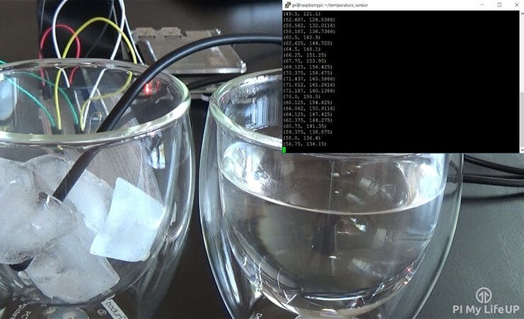
sudo python temperature_sensor.pyCopy15. You should now have an output of temperatures in both Fahrenheit and Celsius. You can alter this just to display your preferred temperature scale if you like.
That’s everything you need to know for getting the DS18B20 temperature sensor working with your Raspberry Pi.
If you’re looking to extend this one step further, then be sure to check out my tips below. I will be looking at incorporating this sensor into future projects, so stay tuned.
Possible Further Work
There are quite a few more things you’re able to do with this Raspberry Pi temperature sensor. I will quickly mention a couple of ideas, and some of them I may cover in the future.
You can have the Python script connect to a database such as MYSQL and store the data that way. If you add a timestamp to the data, you will be able to look back on data in the future and compare any changes.
This next tip would work great with the one above. You can use data stored in the MySQL database to make pretty graphs showing temperature over the course of a day, month, or even a year. You could make it plot a graph in real time, too.
Alternatively, using influxDB along with Grafana is a great way of visually displaying your temperature statistics.
Conclusion
I hope you have been able to build and get this Raspberry Pi temperature sensor working.
If you have reached this point in the tutorial, we hope you have successfully set up your Raspberry Pi to work as a temperature sensor.
The DS18B20 sensor we used in this guide works perfectly with the Pi, and reading its temperature data is a simple process.
If you have encountered any problems, have feedback, or anything else, please feel free to leave a comment below.
To explore what else you can do with your device, be sure to check out some of our many Raspberry Pi projects.


im getting very frustrated im trying to do this after being away from it for a long time. all of these tutorial seem to fall apart at the point where im trying to do something with python. in this tutorial its at
Permission denied
sorry but i fell there is something besides my lack of experience at play here.
Hi Gregory,
Sorry to hear that you are having issues with this tutorial. I have made some rather large changes to the flow of the tutorial to hopefully make it a bit easier to follow.
The issue you are running into is likely caused by you trying to “git clone” from within a directory that your current user doesn’t own. The guide has been updated to avoid this problem by returning you to your home directory.
Please feel free to comment again if you are still running into issues.
Kind regards,
Emmet
Any chance of this being updated for Debian 12/13 on a Raspberry Pi? The instructions as is work fine on an a 2023 released RaspiOS, but not Bookworm/Trixie
Hi Erik,
This should be working fine as far as I can understand, could you please list any errors that you are running into.
You can also try running the following command to ensure that lgpio package is available.
Kind regards,
Emmet
Danke für die Mega Anleitung, hat geklappt 🙂
Admin Edit: [Google English Translation]: Thanks for the mega instructions, it worked 🙂