In this tutorial, I will be looking at how to set up the Arduino DS18B20 temperature sensor and anything else you need to know about it.
This project is pretty cool if you want to set up a data logger or just something to monitor the temperatures of a certain room. You could combine this tutorial with another to create a pretty cool smart sensor.
You could use something like a piezo buzzer to alert you if the temperature falls outside a certain range for example.
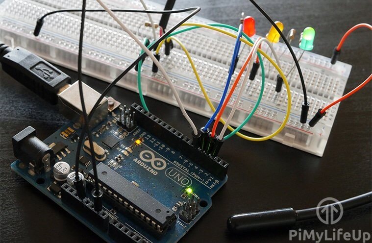
Throughout this tutorial, I will show you the basics of connecting the DS18B20 to the Arduino correctly. I will also be adding some LEDs to demonstrate the circuit & code functionality.
If you want to stay up to date with all my projects and much more, then be sure to follow me on any of the major social networks.
Equipment
In this tutorial, I am going to use some LEDs to represent the current temperature of the temperature sensor. If you just wish to stick with just software, then you don’t need to add these.
You can find the full list of equipment right below.
Recommended
- Arduino Uno Amazon
- DS18B20 temperature sensor Amazon
- 4.7k ohm Resistor Amazon
- Breadboard Amazon
- Breadboard wire Amazon
Optional
Video
The video below will go through all the steps you need to take to getting this cool temperature sensor project up and running.
If you prefer written tutorials, then you can find it right underneath the video.
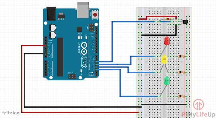
The Arduino DS18B20 Circuit
The circuit for the Arduino DS18B20 sensor is pretty simple and if you don’t want the LEDs just leave that part of the circuit out.
I will just quickly describe the temperature sensor below however the rest of the equipment is pretty straightforward and doesn’t really need explaining.
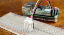
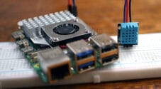
If you have read my guide on the DS18B20 with the Raspberry Pi, then you will know exactly what this device is. For anyone who hasn’t, the DS18B20 is a digital temperature sensor that is capable of reading temperatures within 0.05°C.
The DS18B20 also has one wire support which means it’s capable of sharing a single wire with other devices that also support one wire.
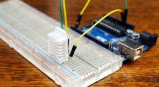
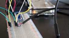
In this tutorial, I use a waterproof version of the DS18B20, so it just looks like a long thick wire with 3 wires sticking out of 1 end. If you get the device without any extras, it simply looks like a regular transistor.
Now let’s move on to putting the circuit together.
1. First, connect the 3v3 pin from the Arduino to the positive rail & a ground pin to the ground rail on the breadboard.
2. Now place the DS18B20 sensor onto the breadboard.
3. Place a 4.7k resistor between the positive lead (Red Wire) and the output lead (White Wire) of the sensor.
4. Next, place a wire from the positive lead (Red Wire) to the positive 3v3 rail.
5. Place a wire from the output lead back to pin #5 on the Arduino. Place a wire from the ground lead (black wire) to the ground rail.
6. Now the next few steps are optional and are only required if you want the LEDs.
7. Place a wire from the ground rail to the ground rail on the opposite side of the breadboard.
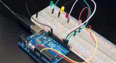
8. Place the 3 LEDs onto the breadboard. (Red, Yellow and Green)
9. Connect a 100-ohm resistor to each LED and have this go to the ground rail.
10. Now have a wire come from the following Arduino pins: pin 2 to the green LED, pin 3 to a yellow LED and finally red to pin 4.
11. Now that’s the circuit all set up, it’s now time to move onto the code. If you come across any trouble with the circuit, please refer to the diagram below or leave a comment at the bottom of this page.
Installing One Wire Support
Now by default, the Arduino doesn’t have one wire support so we will need to download and install the library for this. If you want some extensive information on what is one wire, then be sure to check Arduino’s official website.
Now, this is a pretty straightforward process that I will take you through now.
1. Firstly, download the latest version of the One Wire library, you can download it from their GitHub.
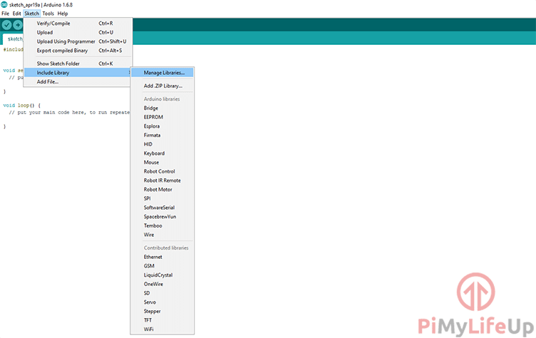
2. Once downloaded open up sketch.
3. In here go up to sketch, include library and then add .zip library.
4. It should now say something like Library added to libraries. Check “include library” menu.
5. So now go back up to sketch, include library and then under contributed libraries you will find onewire, click on it.
6. This process will add a #include at the top of your file and will be added to your Arduino at the next upload.
Installing Dallas Temperature Library
To make things a lot easier, I am going to suggest installing a library to handle the data that comes from the sensor. This library will make it a lot easier than to write the data processing code yourself.
If you want to do it yourself without an additional library, then be sure to check out this one wire page for more information. Alternatively, you can look at an analog sensor such as the TMP36 which is super easy to get going on the Arduino.
If you’re happy using the Dallas temperature sensor library then simply do the following.
1. First, download the Dallas temperature sensor library, you can download it from their GitHub.
2. Now once that has downloaded go into the sketch application and repeat the steps we did before.
3. Go to sketch, include library and then add .zip library.
4. It should now say something like Library added to libraries. Check “include library” menu.
5. So now go back up to sketch, include library and then under contributed libraries you will find DallasTemperature. Click on it.
6. This will automatically add a #include at the top of the script. The library will be synced with your Arduino when you upload it.
Now let’s move onto writing the rest of the code to both get the temperature from the sensor and turn on the correct LED.
Arduino DS18B20 Code
This next part of the tutorial I will go through the code for reading the sensor. It’s pretty straightforward however if you’re new to coding it may be a little overwhelming.
If you want to download the code, then you can find it available for download over at GitHub.
To begin, we need to include both of the OneWire and the dallasTemperature headers so we can use these within the code. These should already be there if you followed the steps above.
#include <OneWire.h>
#include <DallasTemperature.h>Copy
Next, we declare all the variables that we will need to use throughout the script. The first of these represent the pin numbers that the devices are connected to.
The float temperature variable is where we will be storing our temperature value.
The lowerLimit & upperLimit variables represent our threshold temperatures. Anything below the lower limit will trigger the yellow LED to turn on. Anything above the upper limit will turn on the red LED. Anything between these will turn on the green LED.
int greenLedPin = 2;
int yellowLedPin = 3;
int redLedPin = 4;

int temp_sensor = 5;

float temperature = 0;
int lowerLimit = 15;
int higherLimit = 35;Copy
Next, we create a OneWire object by using our pin we defined earlier (5). If you have a large amount of 1 wire sensors, it’s suggested you split these up across multiple pins. For each sensor make a new Onewire object, for example, OneWire oneWirePin2(temp_sensor2);
Now we create our Dallas Temperature sensor object by passing our OneWire reference into the class.
OneWire oneWirePin(temp_sensor);
DallasTemperature sensors(&oneWirePin);Copy
In our setup function, we activate the Arduino serial interface so we can monitor the output lines in the code. This is also where we need to set up our LEDs to all act as outputs. Lastly, we make a call to sensors.begin(), this will set up our sensor so we can start requesting data from it.
void setup(void){
  Serial.begin(9600);

  //Setup the LEDS to act as outputs
  pinMode(redLedPin,OUTPUT);
  pinMode(greenLedPin,OUTPUT);
  pinMode(yellowLedPin,OUTPUT);

  sensors.begin();
}Copy
In this segment, we have a few output lines to let us know when it has successfully requested all the temperatures of the sensors connected to our onewire pin (5).
We next store the value from the sensors.getTempCByIndex(0) into the temperature variable. If you want to get the Fahrenheit temperature, simply change C to F. For example sensors.getTempFByIndex(0). Also, the 0 refers to which sensor we want information from. 0 = the first sensor, if you had a 2nd sensor, then it would be 1.
void loop(){
  Serial.print("Requesting Temperatures from sensors: ");
  sensors.requestTemperatures();
  Serial.println("DONE");

  temperature = sensors.getTempCByIndex(0);Copy
We then turn all the LEDs to low so that only the correct LED remains on when we run the next segment of code. We also print two statements the first being a simple string that says Temperature is and then the temperature itself. We finish off this text in the next segment of code described below.
  digitalWrite(redLedPin, LOW);
  digitalWrite(greenLedPin, LOW);
  digitalWrite(yellowLedPin, LOW);

  Serial.print("Temperature is ");
  Serial.print(temperature);Copy
This last section compares our temperature values with our predefined values. Depending on the result it will turn the relevant LED on. For example, the first if statement says if the temperature is lower or equal to the lowerLimit value then do this.
Lastly, we also delay for 500ms before looping through the process again.
  //Setup the LEDS to act as outputs
  if(temperature <= lowerLimit){
    Serial.println(", Yellow LED is Activated");
    digitalWrite(yellowLedPin, HIGH); }
  else if(temperature > lowerLimit && temperature < higherLimit){
    Serial.println(", Green LED is Activated");
    digitalWrite(greenLedPin, HIGH);
  }
  else if(temperature >= higherLimit){
    Serial.println(", Red LED is Activated");
    digitalWrite(redLedPin, HIGH);
  }
  delay(500);
}Copy
Troubleshooting
If you come across any trouble, then you will find that there are typically a few things that can go wrong. I will just list some of the issues that you may come across.
- If you’re finding odd results are being returned from the DS18B20 temperature sensor than it is possible it’s not receiving enough power, or you’re requesting data too fast from it.
- To fix the power issue, I would suggest reducing the load on the rail supplying power to the sensor. To reduce the number of times you request data from the sensor increase the delay time to something a bit higher.
- If the sensor is returning consistent high temperatures all the time, then it’s possible it isn’t connected to the breadboard properly. Try making sure the connections are secure before restarting your Arduino.
These issues shouldn’t happen with the default circuit and code from this tutorial, but they may occur if you change things.
I hope this Arduino DS18b20 temperature sensor tutorial has helped with setting up everything correctly. If I have missed something, made a mistake or you just want to leave some feedback, then please feel free to leave a comment below.
For some odd reason can’t get a data reading from my temp sensor. have tried many methods. but i am wondering if this is the problem https://www.amazon.ca/dp/B01D0GEWC2?ref=ppx_yo2ov_dt_b_fed_asin_title
I ordered 10 of these and these are 1/2 watt instead of 1/2 watt. Would that be an issue?
The DS18B20 sensor draws very little current, so even a 1/4 watt resistor should be sufficient. Are you getting any errors running the code, or just no/invalid data?
It is possible that the sensor or breadboard itself is faulty.
thanks for your reply. I went with my hunch and picked up a couple more resistors to try. It was the resistor either a bad order from amazon or?. I need to learn to test resistors.
Hello Gus, I have enjoyed your project, thank you.
I would like to see the LEDs flash when their temp threshold has been triggered. Can you help with this or advise me where I may find someone who can help? Thank you, Eric.