In this tutorial, we will be showing you how to add either the PCF8523, DSL1307 or DS3231 real-time clock (RTC) modules to your Raspberry Pi.
We will be showing you how each of the individual real-time clock chips needs to be wired up to the Raspberry Pi to function correctly by providing the pin numbers and a helpful GPIO guide.
You will also learn in this tutorial how to make the changes to the Raspberry Pi’s configuration, as well as how to modify packages on Raspberry Pi OS so it reads the time from your real-time clock module rather than the fake time it relies on by default.
We will also show you how to set the time on your real-time clock module if it is out of sync with the actual time. This is an issue that only usually occurs if your RTC loses power, or it’s being set up for the first time.
Now, if you are using a Raspberry Pi 5, you don’t have to worry about any of these steps, as the RTC chip built into the board will work straight out of the box and be automatically detected by the Raspberry Pi OS kernel.
You Might Also Like


Equipment List
Below are all the bits and pieces that I used for this tutorial on setting up an RTC with your Raspberry Pi.
Recommended
- Raspberry Pi Amazon
- Micro SD Card Amazon
- Power Supply Amazon
- PCF8523, DSL1307 or DS3231 RTC Modules Amazon
Optional
This tutorial was last tested on a Raspberry Pi 4 running the latest version of Raspberry Pi OS Trixie.
Wiring your RTC module to the Raspberry Pi
On your RTC Module, you should find at least four connections. Some RTC circuits may come with more, but we only need the following four for it to work with the Raspberry Pi:
- VCC/5V/Vin (IC Power-supply pin)
- SDA (Serial Data Line)
- SCL (Serial Clock Line)
- GND (Ground power-supply pin)
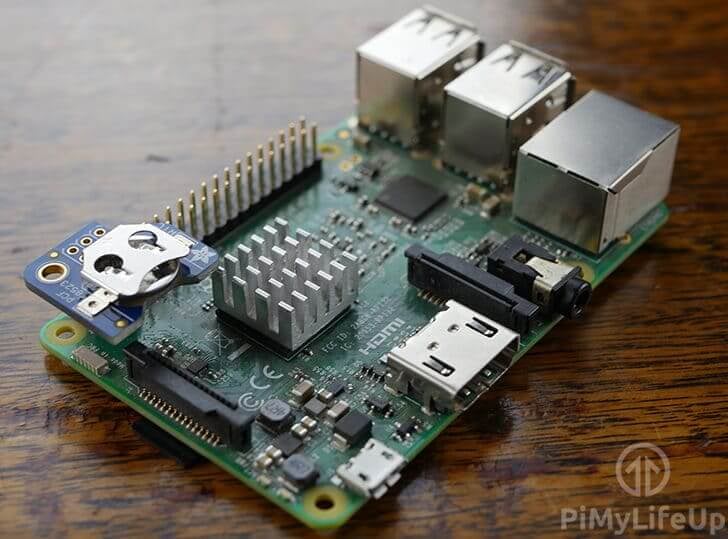
You can either connect these lines directly to your Raspberry Pi or connect it to a breadboard and then to the Raspberry Pi. For this tutorial, we utilized the Pi RTC PCF8523 from Adafruit which plugs in directly over the first six pins which significantly simplifies the process of setting up an RTC (Real Time Clock) module.
However, wiring up a normal PCF8523, DSL1307 and a DS3231 isn’t a complicated process, following our guide below you should have everything connected to in no time.
DS3231 & PCF8523
- Vin connects to Pin 1
- SDA connects to Pin 3
- SCL connects to Pin 5
- GND connects to Pin 6

DS1307
- Vin connects to Pin 4
- SDA connects to Pin 3
- SCL connects to Pin 5
- GND connects to Pin 6

Setting up your Raspberry Pi to use an RTC
In the following sections, we will walk you through the process of setting up your Raspberry Pi to use an attached RTC. By the end of this, you will have your Pi maintaining time much more accurately with the help of an attached real-time clock.
Preparing your Raspberry Pi to use an RTC
1. There are a few things we will need to do before we can actually begin to set up and use the RTC on our Raspberry Pi.
Let’s begin this tutorial by ensuring our Raspberry Pi is entirely up to date; this ensures that we will be using the latest software available.
sudo apt update
sudo apt upgradeCopy
7. Once the Raspberry Pi has finished updating, we need to install an additional two packages. These packages will help us tell whether we have set up I2C successfully, as well as talk with the real-time-clock itself.
Run the following command on your Raspberry Pi to install “i2c-tools” and “util-linux-extra“:
sudo apt install i2c-tools util-linux-extraCopyEnabling I2C
3. With the Raspberry Pi now entirely up to date, we can run its configuration tool to begin the process of switching on I2C. This is the protocol used by most of the popular RTC chips to interface with the Raspberry Pi.
To launch this configuration tool, all you need to do is run the command below.
sudo raspi-configCopy3. This command will bring up the configuration tool; this tool is an easy way to make a variety of changes to your Raspberry Pi’s configuration. Today, however, we will only by exploring how to enable the I2C interface.
Use the ARROW KEYS to go down and select “3 Interface Options“. Once this option has been selected, you can press ENTER.
4. On the next screen, you will want to use the ARROW KEYS to select “I5 I2C“, press ENTER once highlighted to choose this option.
5. You will now be asked if you want to enable the “ARM I2C Interface“, select “<Yes>” with your ARROW KEYS and press ENTER to proceed.
6. Once the raspi-config tool makes the needed changes, the following text should appear on the screen: “The ARM I2C interface is enabled“.
You can now quit out of the tool by pressing ESC until you return to the terminal.
Setting up the Raspberry Pi to Talk with the RTC
7. Now that we have the I2C protocol enabled on our Raspberry Pi, we need to get it to actually understand how to use it to talk with our chosen RTC chip.
To achieve this, we must modify the boot configuration file so that it selects the correct kernel driver. This sounds more intimidating than the actual process itself.
To begin editing the “/boot/firmware/config.txt” file on our Raspberry Pi, use the following command in the terminal..
sudo nano /boot/firmware/config.txtCopy8. Within this file, you will want to add one of the following lines to the bottom of the file. Make sure you use the correct one for the RTC Chip you are using. In our case, we are using a PCF8523.
DS1307
dtoverlay=i2c-rtc,ds1307CopyPCF8523
dtoverlay=i2c-rtc,pcf8523CopyDS3231
dtoverlay=i2c-rtc,ds3231Copy9. Once you have added the correct line for your device to the bottom of the file, you can save and quit out of it by pressing CTRL + X, then Y and then ENTER.
10. Since we have changed the boot configuration, we must restart our Raspberry Pi. Restarting ensures that when your Pi boots, it uses the kernel driver you specified to communicate with the RTC.
Run the following command on your Raspberry Pi to restart it.
sudo rebootCopyVerifying that I2C is Enabled and your Pi can see your RTC
11. With those tools now installed, run the following command on your Raspberry Pi to detect that you have correctly wired up your RTC device.
sudo i2cdetect -y 1CopyIf you have successfully wired up your RTC circuit, you should see UU appear in row 60, column 8, as we have shown below. This id is the address of the DS1307, DS3231, and the PCF85231 RTC Chips.
Please note that if you see the number “68“, it means that for some reason your RTC chip is not talking with your Raspberry Pi and that the address is currently in use.
     0  1  2  3  4  5  6  7  8  9  a  b  c  d  e  f
00:                         -- -- -- -- -- -- -- --
10: -- -- -- -- -- -- -- -- -- -- -- -- -- -- -- --
20: -- -- -- -- -- -- -- -- -- -- -- -- -- -- -- --
30: -- -- -- -- -- -- -- -- -- -- -- -- -- -- -- --
40: -- -- -- -- -- -- -- -- -- -- -- -- -- -- -- --
50: -- -- -- -- -- -- -- -- -- -- -- -- -- -- -- --
60: -- -- -- -- -- -- -- -- UU -- -- -- -- -- -- --
70: -- -- -- -- -- -- -- --
12. The other method we can use to verify that your RTC chip is actually talking with your Raspberry Pi is to use grep on the kernel message log.
From this, we can see when the RTC is read by our Raspberry Pi and its time is used to set the system time.
dmesg | grep -i rtcCopyIf everything has worked properly, you will see a message similar to the one below. You can see that our RTC was registered as “rtc0” and that it was used to set the system clock.
[    1.719139] rpi-rtc soc@107c000000:rpi_rtc: registered as rtc0
[    1.726379] rpi-rtc soc@107c000000:rpi_rtc: setting system clock to 2026-01-18T10:27:46 UTC (1768732066)
Syncing time from the Pi to the RTC module
Now that we have our RTC module hooked up and successfully communicating with our Raspberry Pi, we need to synchronize the system time with the RTC module.
The main reason for this is that the time provided by a new RTC module will likely still be set to whatever it was when it left the factory. RTC chips only maintain the time while a power source is connected, and traditionally, RTC chips aren’t shipped with batteries pre-installed.
1. You can read the time directly from the RTC module by running the following command. If you try it now, you will notice it is currently way off our current real-time.
sudo hwclock -v -rCopy2. Now, before we go ahead and sync the correct time from our Raspberry Pi to our RTC module, we need to run the following command to make sure the time on the Raspberry Pi is in fact correct.
If the time is not right, make sure that you are connected to a Wi-Fi or Ethernet connection.
dateCopy3. If the time displayed by the date command is correct, we can go ahead and run the following command on your Raspberry Pi.
This command will write the time from the Raspberry Pi to the RTC Module.
sudo hwclock -wCopy4. Now if you read the time directly from the RTC module again, you will notice that it has been changed to the same time as what your Raspberry Pi was set at.
You should never have to rerun the previous command if you keep a battery in your RTC module.
sudo hwclock -rCopyConclusion
You should now have a fully operational RTC module that keeps your Raspberry Pi’s time correct even when it loses power or an internet connection. I hope you have enjoyed this fun Pi project and will put it to good use.
If you have any questions, queries, thoughts, or anything else on this tutorial on setting up an RTC with your Raspberry Pi, then be sure to leave a comment below.


Hi Emmet,
Your advice solved the problem, great job, you are my hero.
Many regards
Gerry