In this Raspberry Pi distance sensor tutorial, we will be utilizing the HC-SR04 Ultrasonic Sensor with our Raspberry Pi.
This guide will go through showing you how to wire up the sensor with the Raspberry Pi as well as exploring how we can utilize the sensor also to read distance.
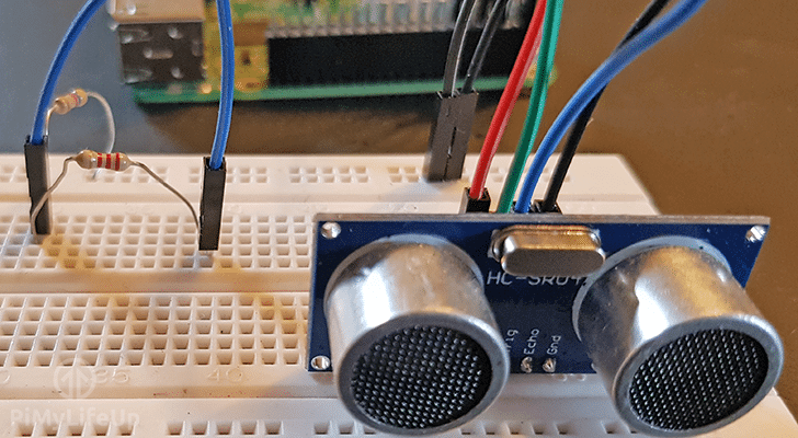
We will be showing you how to wire the HC-SR04 sensor up to the Raspberry Pi, including how to wire a voltage divider as the circuit requires one to drop the 5v output from the sensor to 3.3v for the Raspberry Pi.
This is just one of many sensors you can use with your Raspberry Pi, if you’re interested in more, then be sure to check out our Raspberry Pi sensor tutorials section.
Including showing how to wire up the sensor to the Raspberry Pi, we also explore writing a Python script that will utilize the HC-SR04 Ultrasonic sensor to calculate distance.
We achieve this by measuring the time it takes the ultrasonic pulse being sent out to it being received back by the sensor.
Equipment List
Below are all the bits and pieces that we utilized for this guide on setting up a Raspberry Pi distance sensor circuit
Recommended
- Raspberry Pi Amazon 2 or newer
- Micro SD Card Amazon
- Power Supply Amazon
- HC-SR04 Ultrasonic Sensor Amazon
- 1k OHM Resistor Amazon
- 2k OHM Resistor Amazon
- Breadboard Amazon
- Breadboard Wire Amazon
Optional
Raspberry Pi Distance Sensor Hardware Setup
In this section, we will be showing you how to wire your HC-SR04 Distance Sensor to your Raspberry Pi. Wiring your sensor is a relatively simple process as most pins of the distance sensor map directly to a pin on the Raspberry Pi.
The only slightly complicated part of wiring the device to the Raspberry Pi is the voltage divider that we set up for the echo pin.
The reason for adding a voltage divider is to drop the voltage going to the GPIO pins down to 3.3v from 5v. In this guide, we will be utilizing a 1k Ω resistor and a 2k Ω resistor to achieve this. If you want to understand how we calculate the values of a voltage divider, you can check out the guide featured at the end of this book.
Follow the guides below to see how to wire your HC-SR04 distance sensor to your Raspberry Pi.
- VCC Connects to Pin 2 (5v)
- Trig Connects to Pin 7 (GPIO 4)
- Echo Connects to R1 (1k Ω)
- R2 (2k Ω) Connects from R1 to Ground
- Wire from R1 and R2 connects to Pin 11
- GND connects to Pin 6 (Ground)
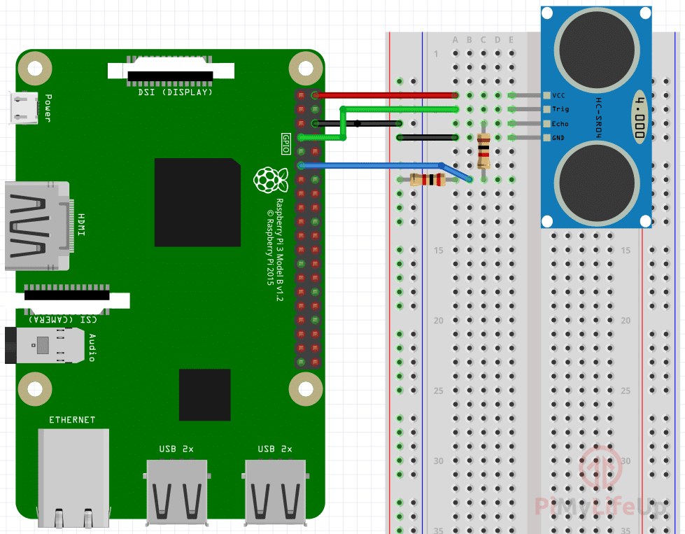

To construct the circuit just do the following.
Don’t forget you can use the diagram above to give yourself an idea of what you need to do.
1. Run a wire from the ground pin (Pin 6) to the ground/negative rail on the breadboard.
2. Run a wire from 5v pin (Pin 2) to the VCC pin on the HC-SR04 distance sensor.
3. Run a wire from pin 7 to the TRIG pin on the distance sensor.
4. Run a 1k Ω resistor from the ECHO pin on the distance sensor to a spot on the breadboard.
5. Run a 2k Ω resistor from the 1k Ω resistor to the ground/negative rail on the Raspberry Pi.
6. Run a wire from between the 1k Ω resistor and the 2k Ω resistor to pin 11 on the Raspberry Pi.
Utilizing your Raspberry Pi Distance Sensor
1. To utilize our Raspberry Pi Distance Sensor we luckily only have to program up a python script. Since we only use GPIO pins to interact with the distance sensor, there is no need to mess around with the raspi-config tool.
Before we begin writing our script, lets first make a folder to keep it. Run the following two commands on your Raspberry Pi to create the folder and change directory to it.
mkdir ~/distance_sensor/
cd ~/distance_sensor
2. Now that we are in our new directory, let’s begin writing our distance sensor python script by running the following nano command on the Raspberry Pi.
nano distance_sensor.py3. Within this file, write the following lines of code. We will explain the important parts of each block of code as we write it. Remember when writing in Python code that it is whitespace sensitive, so make sure that you retain the tabs that we have put in.
#!/usr/bin/python
import RPi.GPIO as GPIO
import time

try:
The first line tells the shell what we should be utilizing to run our Python file. Without it, there is no guarantee our file will be interpreted by Python.
We then proceed to import the two libraries that we need to write our script and interact with the distance sensor from our Raspberry Pi. The two libraries that we import are the following:
Rpi.GPIO – This is the package that allows us to control and interact with the GPIO pins, without this package we wouldn’t be able to talk with our distance sensor.
time – This package allows us to control time-related functions with the script. We mainly just use this to put the script to sleep and also time how long it takes to receive data back from the sensor.
Finally, we begin our try: statement, we cover the vast majority of the code within this to ensure that we clear the GPIO pins on exit.
      GPIO.setmode(GPIO.BOARD)

      PIN_TRIGGER = 7
      PIN_ECHO = 11

      GPIO.setup(PIN_TRIGGER, GPIO.OUT)
      GPIO.setup(PIN_ECHO, GPIO.IN)
On the first line here we set our GPIO mode to GPIO.BOARD, this means we are using the physical pin numbers and not the BCM numbers. We use this to ensure compatibility with our script as the BCM Numbers are not guaranteed to stay the same.
Next two lines we create two variables to store the physical pins that we have the trigger and echo wired to. We define them here to make it easy to change them without having to sift through the code continually.
Next we setup both our pins to either expect an output or an input. Our trigger pin is obviously an output pin as we need to ping this pin to start the sensor. The Echo pin is where we expect our data from, so we set this to receive input.
      GPIO.output(PIN_TRIGGER, GPIO.LOW)

      print "Waiting for sensor to settle"

      time.sleep(2)
The first line we set our PIN_TRIGGER GPIO Pin, so it doesn’t send out anything by setting it to “Low”. We do this to let our HC-SR04 sensor settle. This ensures we should be getting more consistent readings.
We then proceed to sleep the script for 2 seconds to ensure we give the distance sensor enough time to settle and don’t immediately start triggering it.
      print "Calculating distance"

      GPIO.output(PIN_TRIGGER, GPIO.HIGH)

      time.sleep(0.00001)

      GPIO.output(PIN_TRIGGER, GPIO.LOW)
Finally, we get to the piece of code which gets the HC-SR04 distance sensor to trigger. To do this, we need to first set our PIN_TRIGGER to high.
We then need to sleep the script for 1 nanosecond, the reason for this is that the HC-SR04 distance sensor requires a pulse of 1 nanosecond to trigger it.
Immediately after the sleep has completed, we set PIN_TRIGGER low again.
      while GPIO.input(PIN_ECHO)==0:
            pulse_start_time = time.time()
      while GPIO.input(PIN_ECHO)==1:
            pulse_end_time = time.time()

      pulse_duration = pulse_end_time - pulse_start_time

      distance = round(pulse_duration * 17150, 2)

      print "Distance:",distance,"cm"
First, we run a while loop to continually check if PIN_ECHO is low (0) if it is we continually set the pulse_start_time to the current time until it becomes high (1)
Once PIN_ECHO reads high, we set pulse_end_time to the current time. We do this until PIN_ECHO is set to low again.
These two loops allow us to calculate the time that it took for the ultrasonic pulse to be sent out and received back. Once we have both times, we just minus the two saved times to work out the duration.
With the pulse duration calculated we can work out the distance, it traveled since we know the rough speed of ultrasonic sound is 34300 cm/s.
Since the duration of the pulse is the time it took for the ultrasonic sound to hit an object and bounce back, we will just use half the speed to calculate the distance it traveled before returning. Doing this is a simpler calculation then calculating the distance with the full speed then dividing by 2.
So finally our distance is equal to the duration of the pulse, multiplied by 17150 cm/s.
finally:
      GPIO.cleanup()
These two final lines of code are quite crucial as it ensures an end to our try: statement and ensures that we run GPIO.cleanup() when the script is terminated in any way. Failing to do so will throw warnings when rerunning the script or any other script that makes use of the GPIO pins.
4. Once you have finished typing in all the code, you should end up with something that looks like what we have below.
#!/usr/bin/python
import RPi.GPIO as GPIO
import time

try:
      GPIO.setmode(GPIO.BOARD)

      PIN_TRIGGER = 7
      PIN_ECHO = 11

      GPIO.setup(PIN_TRIGGER, GPIO.OUT)
      GPIO.setup(PIN_ECHO, GPIO.IN)

      GPIO.output(PIN_TRIGGER, GPIO.LOW)

      print "Waiting for sensor to settle"

      time.sleep(2)

      print "Calculating distance"

      GPIO.output(PIN_TRIGGER, GPIO.HIGH)

      time.sleep(0.00001)

      GPIO.output(PIN_TRIGGER, GPIO.LOW)

      while GPIO.input(PIN_ECHO)==0:
            pulse_start_time = time.time()
      while GPIO.input(PIN_ECHO)==1:
            pulse_end_time = time.time()

      pulse_duration = pulse_end_time - pulse_start_time
      distance = round(pulse_duration * 17150, 2)
      print "Distance:",distance,"cm"

finally:
      GPIO.cleanup()
With the code entered in properly then you can save the file by pressing CTRL + X then Y and pressing ENTER.
5. Now that you have successfully written the script we can run it by running the following simple command on your Raspberry Pi.
python ~/distance_sensor/distance_sensor.py6. If everything is working correctly, you should get something like what is shown below in your terminal. Of course, the distance will be different to what we got.
Waiting for sensor to settle
Calculating distance
Distance: 29.69 cm
Conclusion
Hopefully, by now you will have successfully set up your Raspberry Pi distance sensor and also written a python script that interacts with the sensor and successfully calculates the distance.
If you’re looking to extend this project then you might want to check out the 16×2 LCD tutorial. It will be the perfect way to display the distance without needing to connect a monitor to the Raspberry Pi.
Feel free to drop a comment below if you enjoyed this tutorial on setting up an HC-SR04 distance sensor with your Raspberry Pi or need some help getting it up and running.
I’ll try again, my last attempt didn’t put the code in a code block and it was horribly formatted.
The loop to measure the pulse width could be improved by not setting the time each loop cycle. Do this instead:
This (in theory) will make the loops run just that tiny bit faster and give you better accuracy. Note though, this kind of code is likely to hog the CPU with or without the change.
I am getting the following error message.
Can you please help me on this?
Somehow it’s getting to line 34, and pulse_end_time hasn’t been defined.
An easy way to fix this would be to define these at the start of the program. However, that may end up hiding an underlying problem.
To define the variables, simply add the following two lines underneath PIN_ECHO = 11.
I would also double check the circuit to make sure it’s correct.
My code gets stuck in the while loop
( while GPIO.input(PIN_ECHO)==0:
pulse_start_time = time.time())
What could be the reason for this?
Hi Yosef,
It may be that you have wired your distance sensor to your Raspberry Pi incorrectly or the sensor itself is not function correctly.
The only reason your code will get stuck in that loop is if the input from PIN_ECHO is never equal to 0
Cheers,
Emmet
How do you convert from metric to inches?
Simply divide the cm value by 2.54
For example.
Hi, when I try to run the code it says: ImportError: No module named ‘RPi’
The module RPi is likely not installed. If you’re using Python 3, you can install it using two commands.
Hi, couple of questions:
1) Can I use Raspberry Pi Zero for it? How big of a difference will it make?
2) Is their any top limit on how many Ultrasonic sensors can be handled? I might need up to 100 sensors.
Thanks
Hi YC,
1)
This project should be fine for the Raspberry Pi Zero, the distance sensor doesn’t really require the extra processing power of the Raspberry Pi B series.
2)
You will be limited by the amount of GPIO pins that the Pi has, especially with dealing with such a large number of sensors. You would likely need to use multiple Pi’s to power and handle 100 sensors.
Hi, I’ve tried to connect the sensor without the resistors and it worked ok. Can I leave it like that? Why are the resistors necessary?
Thanks.
Alejandro
Hi Alejandro,
As we explain within the tutorial we recommend that you use the resistors.
The Raspberry Pi’s GPIO pins are only really meant to take a 3.3v power input, but the HC-SR04 outputs at 5V which can damage the Raspberry Pi.
Cheers,
Emmet
The diagram shows the ground connections going to the positive rail on the breadboard. That would be a big mistake if wired up that way, no?
Hi Justin,
The colours next to the rails are only really there as a guide, as long as you are using positive on one rail and negative on the other there is no issue.
Cheers
Step 4 is missing
distance = round(pulse_duration * 17150, 2)
Thank you, I have fixed it up now.