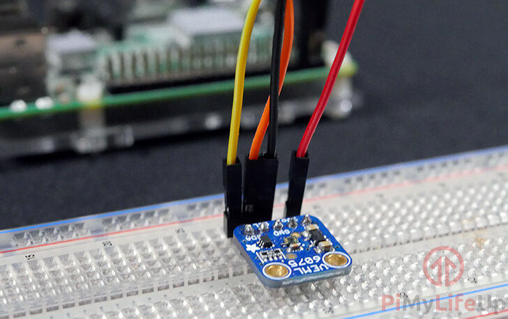
In this project, we will be walking you through the process of connecting the VEML6075 ultraviolet (UV) sensor to the Raspberry Pi.
Alongside wiring the UV sensor to the Raspberry Pi we will be showing you how you can interact with the sensor by utilizing the Python programming language.
To make this entire tutorial work, we will be making use of Adafruit’s VEML6075 library. This library handles most of the grunt work by doing all the necessary calculations for working out the UV index and reading the UVA and UVB values from the UV sensor.
The VEML6075 UV Sensor is a dual-band sensor that senses both UVA (ultraviolet A/longwave) and UVB (ultraviolet B/shortwave) light bands.
One of the best things about this sensor is that it provides its data over the I2C serial protocol, making it very simple to interact with.
You can bundle this sensor with the many other sensors that work with the Raspberry Pi. For example, using a variety of sensors, you could build your own weather station.
Equipment
Below is a list of equipment that you may need for setting up the VEML6075 UV sensor with the Raspberry Pi.
Recommended
Optional
- Breadboard Amazon
- Raspberry Pi Case Amazon
- USB Keyboard Amazon
- USB Mouse Amazon
- HDMI Cable Amazon
- Monitor Amazon
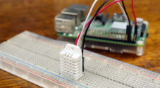
Raspberry Pi VEML6075 UV Sensor Setup
In this section, we will show you the process of connecting the VEML6075 UV Sensor to the Raspberry Pi.
Thanks to the VEML6075 UV sensor being a digital sensor, we can interact with it directly from the Raspberry Pi and not have to rely on additional hardware such as an analog to digital converter (ADC).
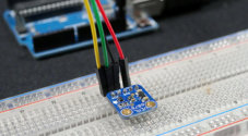
Follow our written guide below to learn all the steps to connecting the VEML6075 to your Raspberry Pi.
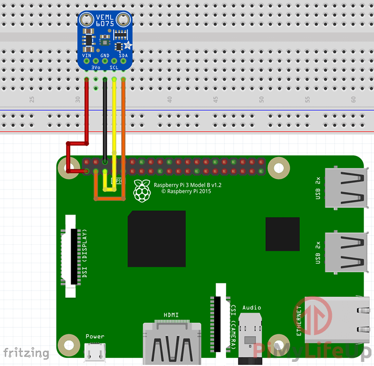
You can either follow the diagrams or utilize our written steps on which wires of the VEML6075 goes to the Raspberry Pi GPIO pins.
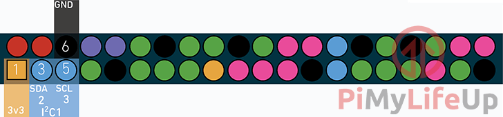
- Wire the VIN pin of the VEML6075 UV Sensor to Physical Pin 1 (3v3) on the Raspberry Pi.
- Wire the GND pin of the VEML6075 UV Sensor to Physical Pin 6 (GND) on the Raspberry Pi.
- Wire the SDA pin of the VEML6075 UV Sensorto Physical Pin 3 (SDA) on the Raspberry Pi.
- Wire the SCL pin of the VEML6075 UV Sensor to Physical Pin 5 (SCL) on the Raspberry Pi.
Setting up your Raspberry Pi for the VEML6075 UV Sensor
1. Before we get started interacting with the VEML6075 UV sensor on our Raspberry Pi, there are a few things we must first do.
The first thing we need to do is ensure that our package list and all installed packages are at their latest available versions.
We can check and update by running the following commands.
sudo apt-get update
sudo apt-get upgrade
2. When your Raspberry Pi has finished updating, you can then proceed on to switching on I2C mode for the Pi’s serial interface.
We can do that by launching the Raspberry Pi configuration tool with the following command.
sudo raspi-config3. Within this tool, go ahead and select the “5 Interfacing Options” option.
Navigate the raspi-config tools menus by using the ARROW keys, and the ENTER key.
4. Within interfacing options menu, go ahead and select the “P5 I2C” option.
When asked if you would like to enable the ARM I2C interface, select “<YES>“.
5. Enabling I2C won’t come into effect until you restart the Raspberry Pi. You can reboot the Raspberry Pi by running the following command.
sudo reboot6. With the I2C protocol now enabled on the Raspberry Pi, we can now proceed to install the packages that we will be relying on.
Install the various Python packages that we require by running the following command.
sudo apt-get install python3-dev python3-pip python3-smbus i2c-tools -y7. Now that all the required packages are installed we can use the “i2cdetect” program to see whether the Raspberry Pi can detect our VEML6075 UV sensor.
We can use the i2cdetect program by running the following command.
sudo i2cdetect -y 1This command will output a fair bit of information with many results being marked by hyphens. Within this result, you should see a number such as “10“.
If only hyphens appear in the result, that means the Raspberry Pi can not detect your UV sensor, check all your wiring then try rerunning the command.
If you see an error try re-enabling I2C again.
Coding a Script to talk with the VEML6075 UV Sensor
1. Now that we have adequately prepared our Raspberry Pi to be able to interact with the VEML6075 UV sensor, we can proceed to put everything together.
To quickly read data back from the VEML6075 UV Sensor, we will be making use of the Adafruit VEML6076 CircuitPython library. We can install this library by running the command below.
sudo pip3 install adafruit-circuitpython-VEML60752. Now that we have the library installed, we can now proceed to write a script. The script utilizes the library to calculate the UV index based on the readings from the sensor.
Begin writing this file by running the following command.
nano ~/uvsensor.py3. Within this new UV sensor script go ahead and enter the following lines of code.
import time
import board
import busio
import adafruit_veml6075
In this section, we import all the libraries that our Raspberry Pi ultraviolet sensor script will be relying on.
We import the “time” library so that we can use the “sleep()” function to put the script to sleep for a certain amount of time.
Next, we import the “board” library. This library is from Adafruit’s CircuitPython collection and is utilized to obtain the correct pin numbers for the current board easily.
The “busio” library is another Adafruit CircuitPython library. This library is used as a standard way of handling serial connections. For this guide, we will be using it to set up an I2C connection that we will pass into the VEML6075 library.
Finally, we have the “adafruit_veml6075” library. This library is utilized to read all the values from the UV sensor and calculate values such as the UV index.
i2c = busio.I2C(board.SCL, board.SDA)This line instantiates the “busio” object utilizing its “I2C()” function. This function sets itself up to connect with the two pins that we pass through into it, those pins being “board.SCL” and “board.SDA“.
veml = adafruit_veml6075.VEML6075(i2c, integration_time=100)Next, we instantiate the veml6075 library to our “veml” object. To the constructor, we pass in both the “i2c” object we set up in the previous line, as well as the value for the “integration_time“.
The “integration_time” is the amount of time you want the sensor to spend collecting samples, the longer the integration time, the more accurate the sensors readings will be.
while True:
    print(veml.uv_index)
    time.sleep(1)
Now we run an infinite loop by using “while True:“.
Within this infinite loop, we print out out the UV Index value by accessing the “veml” object’s “uv_index” variable.
When we access the “uv_index” variable, the VEML6075 library takes a reading from the UV sensor and calculates the UV Index based on the UVA and UVB readings from the sensor.
Finally, we sleep the script for 1 second using the “time” libraries “sleep()” functionality.
4. Once you have finished entering all the code into the file, it should look like what we have shown below.
import time
import board
import busio
import adafruit_veml6075

i2c = busio.I2C(board.SCL, board.SDA)

veml = adafruit_veml6075.VEML6075(i2c, integration_time=100)

while True:
    print(veml.uv_index)
    time.sleep(1)
You can now save the file by pressing CTRL + X then Y followed by ENTER.
5. Let’s go ahead and now test our “uvsensor.py” script by running the following command.
python3 ~/uvsensor.py6. You should immediately start seeing the UV index being read by your VEML6075 UV Sensor.
We have an example of our UV sensor’s results below. We have used a UV torch to manipulate the results since we were using this inside (Inside lights will give very low results, almost zero or negative).
0.026104000000000002
0.018564999999999998
0.012321499999999999
0.015808500000000003
0.026104000000000002
0.054912825000000005
0.09654692999999999
0.06701715
0.08051291
0.12981893
0.12611369
At this point you should now have your Raspberry Pi UV sensor up and running successfully.
Conclusion
You should now have an understanding of how the VEML6075 sensor is wired to the Raspberry Pi as well as how to read data from the sensor and interpret it.
We have plenty of other electronics projects that you should check out if you enjoyed this one. Also if you have any feedback then please don’t hesitate to leave a comment below.
This code worked first time for me on a RPi 4. Thanks for making it available.