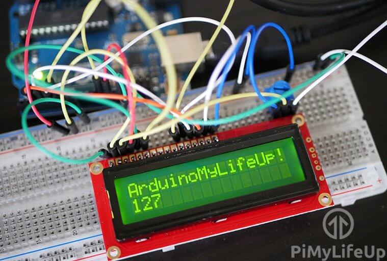
In this Arduino LCD tutorial, I will take you through the steps to connecting a simple 16×2 LCD up to the Arduino.
There is a ton that you’re able to do with an LCD (liquid crystal display), so it’s a useful little device to learn how to connect and communicate with.
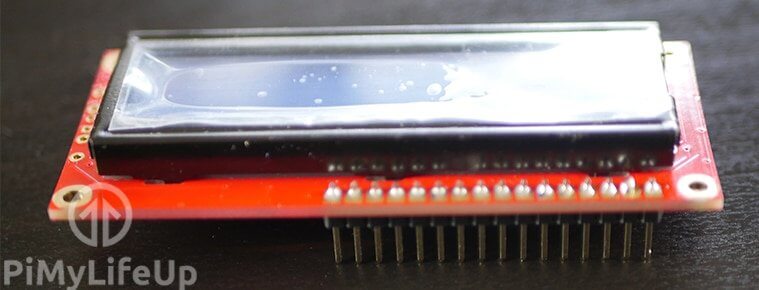
You will find that most LCD boards are not assembled with header pins so these will need to be soldered on. If you have header pins, then this isn’t too much of a task. You can probably skip soldering but getting a good connection to the board will be difficult.
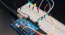
The potentiometer you find in the circuit is used to control the brightness of the screen. If you find nothing is displaying or it doesn’t look right, then try turning this up or down.
At the bottom of this tutorial, I go through some project ideas of what you can do with 16×2 LCD and the Arduino. If you have any ideas that you would like to share, then please don’t hesitate to leave a comment below.
Equipment
The pieces of equipment that I made use of are listed below.
Recommended
- Arduino Uno Amazon
- 16×2 LCD Amazon Board
- 16x Header pins Amazon if LCD display has no pins
- Breadboard Amazon
- Breadboard wire Amazon
- 10k ohm Potentiometer Amazon
Optional
Video
If you want to see how it is all done, then be sure to check out the video below. It goes through all the steps to making sure you hook up the LCD to the Arduino correctly.
If you prefer written tutorials, then you can find everything you need underneath the video.
Soldering the LCD Board Pins
The circuit for the Arduino liquid crystal display is actually surprisingly easy. You will find that the most off-putting thing about it is how many wires that needs to be hooked up.
It’s important to note that you’re likely going to need to solder header pins onto the LCD display. This is a pretty straightforward process.
1. Place the header pins, so the short side sticks up through the holes on the display board.
2. Now solder the pins one by one ensuring you don’t accidentally connect two together. If you do connect two together, then melt the solder and suck it using a solder sucker.
3. Once done it’s ready for use.
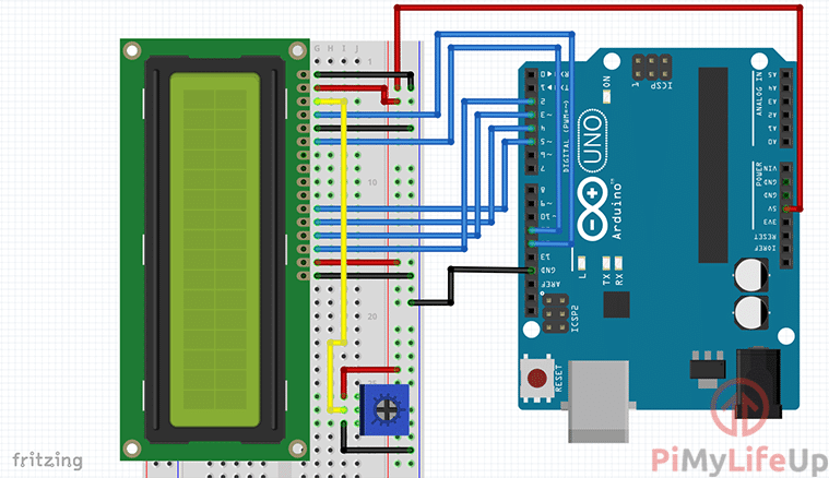
Arduino LCD Circuit
Below are the steps that you will need to follow for hooking up the display. You can find the full circuit diagram right underneath the steps if you rather follow that.
1. First, hook the 5V pin from the Arduino to the positive line on the breadboard.
2. Hook the ground pin to the ground rail on the breadboard.
3. Connect the potentiometer to the breadboard and wire the positive pin to the positive rail. Also, wire the ground pin to the ground rail.
4. Place the following wires to the LCD screen with pin 1 being the closest to the edge of the board.
- Ground rail to pin 1, pin 5 & pin 16 of the LCD.
- Positive 5v rail to pin 2 & pin 15 of the LCD.
- Connect the middle wire on the potentiometer to pin 3 of the LCD.
5. Wire The following Arduino Digital pins to the LCD pins.
- Arduino to the LCD
- Pin 12 to Pin 4
- Pin 11 to pin 6
- Pin 5 to pin 11
- Pin 4 to pin 12
- Pin 3 to pin 13
- Pin 2 to pin 14
That’s all you need to do. If you come across any issues, please refer to the diagram below.
Code to Communicate with the Display
The code for communicating with the display is actually pretty straightforward. You may have thought while connecting the display that the code will be complicated, but gladly it’s not thanks to a helpful library by Limor Fried that’s already included in Arduino’s main library collection.
It’s important to know that there is are already some code examples within the Arduino software. To find them go to File->Examples->LiquidCrystal
In here you will see a range of different examples with each showing you how to use certain methods of the liquid crystal library.
To begin, I suggest taking a look at the hello world example. The code for this example is below.
// include the library code:
#include <LiquidCrystal.h>

//initialise the library with the numbers of the interface pins
LiquidCrystal lcd(12, 11, 5, 4, 3, 2);

void setup() {
  // set up the LCD's number of columns and rows:
  lcd.begin(16, 2);
  // Print a message to the LCD.
  lcd.print("hello, world!");
}

void loop() {
  // set the cursor to column 0, line 1
  lcd.setCursor(0, 1);
  // print the number of seconds since reset:
  lcd.print(millis() / 1000);
}Copy
Setting up the LCD
In the code, you will need to set up a variable of type LiquidCrystal. As you can see below.
LiquidCrystal lcd(12, 11, 5, 4, 3, 2);CopyThe numbers that are passed as parameters represent the Arduino pin number that we have connected to a pin on the display board. Below is an example of the function again, but instead it contains the corresponding pins on the LCD.
LiquidCrystal(rs, enable, d4, d5, d6, d7)CopyThe datasheet for your LCD board will contain the pin number and their type. For example, below is the datasheet for my board. (DB4 = D4, E = enable and so on)
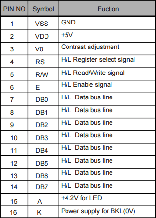
The above function can be extended to read from 8 data lines in total.
LiquidCrystal(rs, enable, d0, d1, d2, d3, d4, d5, d6, d7)Copylcd.begin located in the setup function in the code above is used to initialize the interface to the LCD. Here is where you need to specify how many columns and rows there are on the display.
For example, my display has 16 columns and 2 rows. This means we need to set it up with 16 as the first parameter and 2 as the 2nd parameter lcd.begin(cols, rows)
The Basic Methods of the LCD
If you ever need to clear the display then call the method lcd.clear(); This will wipe the display so that you can display a new value on there. Make sure you have a delay beforehand, so you’re able to see whatever is being displayed on the screen.
Want to move the cursor back to home rather than clearing the display then lcd.home(); will move the cursor to position 1.
If you want to print a string on the LCD display, then the print method is what you need. Just simply call it like this lcd.print("My String");
The last basic method I will mention is called write. This method is used to write a character to the screen. Very much like print simply call it like this: lcd.write('I');
Extra Functions
Below are almost all of the current methods that you’re able to call for the Arduino LCD display. If you want more information on the functions, then you can find the full documentation over at Arduino’s official website.
Auto-scroll: Shift text right and left.
autoscroll(); This will move the text one space to the left whenever a new character is added.
noAutoscroll(); Turns off auto scrolling.
Cursor: This allows you to turn off and on the underscore cursor.
noCursor(); Turns off the underscore cursor.
Cursor(); Turns on the underscore cursor.
Blink: Turns on and off the blinking of the block cursor.
noBlink(); Turns off the blinking cursor.
blink(); Turns on the blinking cursor.
Display: Make the display go blank without losing the current text.
noDisplay(); Turns off the display.
display(); Turns on the display.
Scroll: Allows you to scroll the text both left and right.
scrollDisplayLeft(); Will scroll one position to the left.
scrollDisplayRight(); Will scroll one position to the right.
Serial Display: You can set up the board to accept serial input from something like the serial monitor. You can print the text sent through the serial port on the screen.
write(Serial.read());
Set Cursor: Sets the cursor to a specific position. (Location, Line)
setCursor(0, 0); Will set the cursor to be at the top left.
setCursor(15, 1); Will set the cursor to be at the bottom right.
Text Direction: Allows you to tell which way the text should flow from the cursor.
rightToLeft(); Forces the text to flow from the left of the cursor.
leftToRight(); Forces the text to flow from the right of the cursor.
I have put together a script to show you an example of each of the above methods in order. You will find that the set cursor and serial display options are left out for now.
If you want to run it and give it a go, then you can find it for download over at my GitHub LCD display project page.
Below is an example of the script in action.
Adblock removing the video? Subscribe to premium for no-ads.
Further Work
There is a ton of things that you’re able to do with an LCD screen. I will touch on just a few ideas that I am thinking of covering in the future below. If you have any of your own ideas, then be sure to share them by leaving a comment at the bottom of this page.
One thing you can do is bundle this LCD project with a temperature sensor and have a digital temperature display for your fish tank, fridge, room, outside or wherever you would like to know the temperature.
You will probably want to use one of these if you’re planning on making an Arduino clock. Bundled with the temperature sensor and a button, you could make a smart clock where you can press a button to get the current temperature. One step further would be to add a speaker and have it also act as an alarm clock.
I have covered an Arduino dice circuit before but instead of using the LED’s you could use the LCD to display the outcome of the roll. Just keep the switch and replace the rest with the screen.
There is a huge amount of potential for what you’re able to do with an LCD. I will be looking at future projects that incorporate this cool part.
Now I hope you now have an Arduino LCD display hooked up and working correctly. If I have got anything wrong or you just have some feedback or something to add, then please don’t hesitate to leave a comment below.