In this project, we show you how to wire the APA102 RGB LED Strip to an Arduino Uno.
Within this tutorial, you will learn how to wire the APA102 LED strip so that it uses the Arduino Uno as its controller and retrieves power from an external adapter.
We make use of an external power adapter in our guide as drawing too much current from the Arduino can potentially damage the board.
Alongside showing you how to wire the APA102 and the Arduino together, we will also show you how you can utilize the FastLED library to control the LED strip.
There are plenty of ways you can extend this Arduino project. For example, you can change the colors on the strip to represent the current temperature. Use something like the DS18B20 temperature sensor with the Arduino.
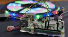
You can also setup the APA102 LED strip with a Raspberry Pi. It’s perfect if you prefer using the Pi for all your projects.
Equipment
To complete this APA102 LED strip project, you will need to pick up a few pieces of equipment.
Recommended
- Arduino Uno Amazon
- APA102 LED Strip Amazon
- Female DC Power Adapter Jack Amazon
- 5V, 10A AC Power Adapter Amazon
- Breadboard Wire Amazon
Setting up the Arduino APA102 LED Strip Circuit
Wiring the APA102 LED circuit to your Arduino is a relatively simple process.
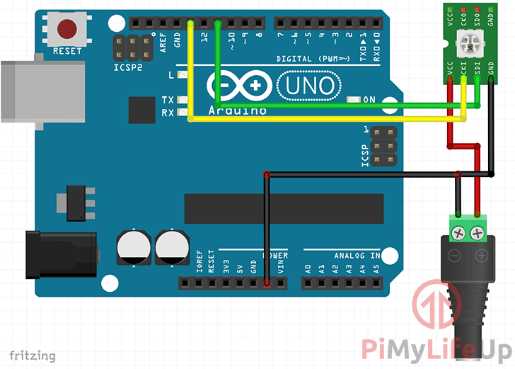
We have included both written instructions as well as a diagram to help you with the process of wiring the APA102 LED strip to an Arduino Uno.
- Wire the Positive Pin (+) of the DC barrel adapter to the VCC connection on the APA102
- Wire the Negative Pin (–) of the DC barrel adapter to both the GND pin on the Arduino and the GND connection on the APA102 LED strip
- Wire the CKI (CI) connection of the APA102 to Pin 11 on the Arduino
- Wire the SDI (DI) connection of the APA102 to Pin 13 on the Arduino
The diagram below should help you out if you get confused on where each which connection needs to be wired.
Pay particular attention to the ground wire that needs to be connected from the APA102 LED strip to both the barrel connector and the Arduino itself.
In this circuit, we made sure we utilized a separate power source to power the APA102 LED strip, which is why we used a DC barrel jack adapter.
The reason for using the DC power adapter is that the Arduino is not capable of maintaining the current needed to power a longer LED strip. The large power draw could potentially damage the Arduino.
Importing the APA102 LED Strip Libraries
To interact with our APA102 RGB LED strip from the Arduino, we will be making use of the “FastLED” library.
The FastLED library is designed to make it easy to interact with all sorts of LED strips, including the APA102 that we are utilizing in this tutorial.
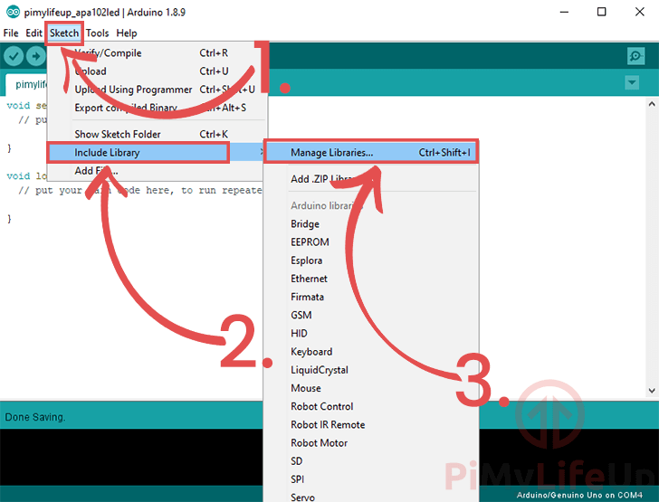
1. Within the Arduino IDE we need to import the “FastLED” library by going to Sketch (1.) -> Include Library (2.) -> Manage Libraries (3.)
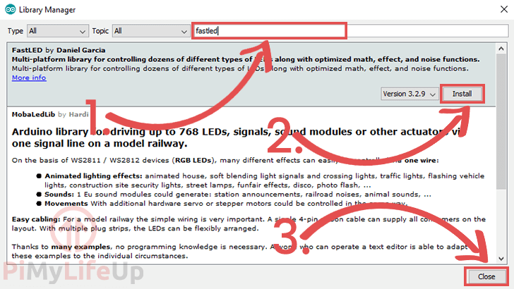
2. Within the Arduino Library Manager, search for “fastled” in the textbox (1.). Next, locate “FastLED by Daniel Garcia” and click the “Install” button (2.).
Once the “FastLED” library has been installed, you can go ahead and click the “Close” button (3.).
Calibrating the RGB LED Strip with the Arduino
Now it’s time to write the code to control our Arduino RGB LED strip.
1. Within the Arduino IDE interface, begin entering the following lines of code.
We will explain what each section of the code does so that you have an understanding of how to modify it for your own needs.
#include <FastLED.h>CopyTo start, we need to include the header file for the “FastLED” library.
This library is what we will be utilizing to send data to our APA102 LED strip. It greatly simplifies the process of interacting with the LED strips.
#define NUM_LEDS 6
#define DATA_PIN 11
#define CLOCK_PIN 13Copy
Here we define a few constants that we will be referencing throughout our code.
NUM_LEDS contains the number of LED’s that you will be dealing with. For this short snippet, we will only need six as we are just looking to calibrate the strip.
DATA_PIN is the pin number that the library should output its data through to control the APA102 strip.
CLOCK_PIN contains the pin number that the library will need to use to send the clock signal. This pin is required for the APA102 strip as it utilizes an SPI interface.
CRGB leds[NUM_LEDS];CopyNext, we define an array called “LEDs” that uses the FastLED’s CRGB as its data type.
This array will be monitored by the FastLED library so that it knows which LED’s need to be lit and the color they need to be.
void setup() {
    delay(2000);
    LEDS.addLeds<APA102,DATA_PIN, CLOCK_PIN,RGB>(leds,NUM_LEDS);
}Copy
This “setup()” function is run upon startup of the Arduino device.
We start by using the “delay()” function. We use this function to give you the chance to reprogram the Arduino if something goes wrong.
Next we utilize the FastLED libraries “addLeds<>()” function. We use this function to set up the library to work with our APA102 LED strip.
To this function, we pass in the model number (APA102) of the LED strip, our DATA_PIN and our CLOCK_PIN constants alongside our color order, which for now is RGB.
We also reference our “LEDS” array we created and our NUM_LEDS. The library will automatically read from our array when we call it’s “show()” function.
void loop() {
    leds[0] = CRGB(255,0,0);
    leds[1] = CRGB(0,255,0);
    leds[2] = CRGB(0,255,0);
    leds[3] = CRGB(0,0,255);
    leds[4] = CRGB(0,0,255);
    leds[5] = CRGB(0,0,255);
    FastLED.show();
    delay(1000);
}Copy
This “loop()” function is automatically run continually by the Arduino after the “setup()” function has finished firing.
Within this loop, we define a value to each spot in our “LEDS” array.
It will light up the first 6 LED’s on our strip and should end up showing in the following order; 1 red, 2 green, and 3 blue. We format the color for each LED by using the “FastLED” libraries “CRGB()” function.
After we have set each value, we utilize the FastLED’s libraries “show()” function to push the new color array to the APA102 LED strip.
Finally, to end the loop, we delay the script for 1 second.
2. The final version of the script should end up looking like as we have shown below.
#include <FastLED.h>
#define NUM_LEDS 6
#define DATA_PIN 11
#define CLOCK_PIN 13
CRGB leds[NUM_LEDS];
void setup() {
delay(2000);
LEDS.addLeds<APA102,DATA_PIN, CLOCK_PIN,RGB>(leds,NUM_LEDS);
}
void loop() {
leds[0] = CRGB(255,0,0);
leds[1] = CRGB(0,255,0);
leds[2] = CRGB(0,255,0);
leds[3] = CRGB(0,0,255);
leds[4] = CRGB(0,0,255);
leds[5] = CRGB(0,0,255);
FastLED.show();
delay(1000);
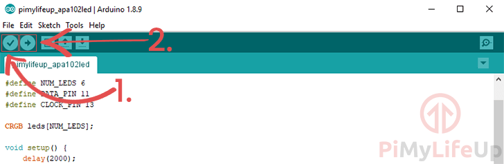
}Copy3. Now we need to push this code to the Arduino. You can do this by first clicking the “Verify” button (1.) then click the “Upload” button (2.).
4. After pushing the code to your Arduino, the APA102 RGB LED strip should light up. Make a note of the order of colors now displayed on the LED strip. It should be Red, Green, and Blue.
If the color order is correct, then you can skip to the next section.
Changing the Color Order
If the color order is incorrect, then make a note of the order. For example, if it has displayed as Blue, Green, and Red, then you need to make a note of the color order being BGR.
Within the code, you need to modify the “LEDS.addLeds” line.
Change the “RGB” color sequence defined to the new one that you just worked out. In this example, we need to switch the value to “BGR“.
The modified line should end up looking something like below.
LEDS.addLeds<APA102,DATA_PIN, CLOCK_PIN,BGR>(leds,NUM_LEDS);Copy5. With the change made, verify and re-upload the code to the Arduino again.
If everything is working correctly, the colors on your LED strip should now be showing in the correct order.
That’s all I have on this Arduino LED strip setup, so I hope that you now have it all working. We have plenty of other great Arduino projects that take you through setting up sensors and other devices. Perfect if you want to extend this tutorial a little.
If you want to leave some feedback, tips, or anything else, then please don’t hesitate to leave a comment below.