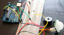
In this Arduino force sensing resistor tutorial, I will be going through all the steps to set up a circuit that can detect pressure placed on a pressure pad or commonly known as a force sensing resistor (FSR).
You can also connect a force sensor resistor to the Raspberry Pi. It is a little more complicated than the Arduino as you don’t have any analog pins on the Raspberry Pi.
There are many uses for a sensor such as this one. Towards the bottom of the tutorial, I go through some example projects that make use of this cool sensor.
The full tutorial on setting up a force sensor with the Arduino is right below. We also go through some simple code to the values from the resistor.
Equipment
Below is the full list of equipment that you will need to complete this Arduino pressure pad tutorial.
Recommended
- Arduino Uno Amazon
- Breadboard Amazon
- Breadboard wire Amazon
- Force Sensor Resistor Amazon (Pressure Pad Amazon )
- 100k Ohm Resistor Amazon
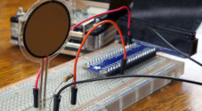
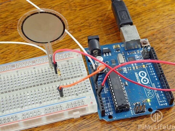
Force Sensing Resistor Circuit
The circuit for this Arduino project is super easy as we only need the force sensing resistor and a 100k resistor.
For this tutorial, I will explain each part and why we will need it in our circuit.
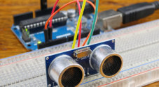
Force Sensor Resistor (FSR)
This resistor is the most important part of the circuit as it will detect whenever pressure is applied to the flat area of the sensor. For this tutorial, I make use of a Flexiforce pressure pad sensor, but there are a lot cheaper alternatives, including making your own.
When there is little to no pressure applied on the sensor the resistance will be near infinite. Once you apply some pressure the resistance drops. It will drop to just under 25k ohms when there is a lot of pressure being applied.
It’s almost exactly the same as a light dependent resistor but relies on force rather than light.
Resistor
This resistor will act as a pull-down resistor and as a voltage divider. It will divide the 5v between the pressure pad and the resistor. When pressure is applied, it will provide enough voltage to register with the Arduino analog pin.
Below is the equation you can work out what the voltage out to our GPIO pin will be. For example, if our pressure pad is max resistance, it will be (100,000 / (100,000 + 10,000,000)) * 5 = ~0.004 volts. This should read 0 when reading from the analog pin.
If you’re applying a quite a bit of pressure to the FSR so that the resistance drops to 50,000 ohms our equation will be (100,000 / (100,000 + 50,000)) * 5 = ~3.3 volts. This should read about 700 on the analog pin.

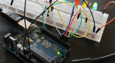
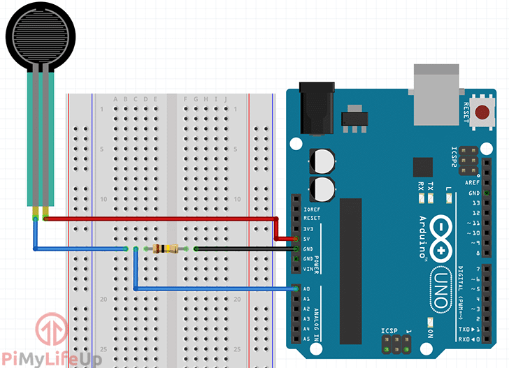
Circuit Diagram
As I mentioned above, the circuit diagram for a force sensing resistor is really straight forward with the Arduino. Either follow the next steps to connect everything or observe the diagram underneath.
- Connect one end of the FSR to 5v.
- Place the 100k resistor onto the breadboard and have one end go to GND and the other to analog pin 0.
- Lastly, have the end of the resistor that goes to analog pin 0 also go the FSR.
Example Video of the Arduino Force Sensor
If you love to see things visually then you can see this project in action right below. I go through the few steps to putting the circuit together and what the serial output should be when you’re applying pressure to the force sensing resistor.
You can find the code required for this project right under the video.
Coding the Force Sensor
The code for this Arduino force sensor circuit is pretty straightforward. You are able to change the code to fit more to your needs but this should be a good starting point.
First, we need to declare our variables. These are mainly defining static values such as which pin our FSR is connected to. We also define what’s considered no pressure, light pressure, and heavy pressure. Lastly, pressurereading is where we will store our value from the sensor.
int pressureAnalogPin = 0;
int pressureReading;

int noPressure = 5;
int lightPressure = 100;
int mediumPressure = 200;Copy
In our setup function, we start the serial interface so we can see the output on our computer. We set the baud rate to the default 9600, change this if you like to use something else.
void setup(void) {
  Serial.begin(9600);
}Copy
Lastly, we have our loop function. In here we first read the reading from the force sensor resistor. We then output this value along with the text “Pressure Pad Reading =“.
Next, we output text to indicate if the pressure being applied is no pressure, light pressure, medium pressure or high pressure.
After the if else block we delay for 1 second and repeat until a new program is uploaded or the Arduino is switched off.
void loop(void) {
  pressureReading = analogRead(pressureAnalogPin);

  Serial.print("Pressure Pad Reading = ");
  Serial.println(pressureReading);

  if (pressureReading < noPressure) {
    Serial.println(" - No pressure");
  } else if (pressureReading < lightPressure) {
    Serial.println(" - Light Pressure");
  } else if (pressureReading < mediumPressure) {
    Serial.println(" - Medium Pressure");
  } else{
    Serial.println(" - High Pressure");
  }
  delay(1000);
}Copy
Below is the entire code for reading our force sensing resistors output. The value that is displayed can be further used for triggering actions based on the amount of pressure applied.
You may need to tweak the variables if you find the pressure values are much higher or lower.
If the copy and paste method isn’t working, then you can also get the code over on our GitHub.
int pressureAnalogPin = 0; //pin where our pressure pad is located.
int pressureReading; //variable for storing our reading

//Adjust these if required.
int noPressure = 5; //max value for no pressure on the pad
int lightPressure = 100; //max value for light pressure on the pad
int mediumPressure = 200; //max value for medium pressure on the pad

void setup(void) {
  Serial.begin(9600);
}

void loop(void) {
  pressureReading = analogRead(pressureAnalogPin);

  Serial.print("Pressure Pad Reading = ");
  Serial.println(pressureReading);

  if (pressureReading < noPressure) {
    Serial.println(" - No pressure");
  } else if (pressureReading < lightPressure) {
    Serial.println(" - Light Pressure");
  } else if (pressureReading < mediumPressure) {
    Serial.println(" - Medium Pressure");
  } else{
    Serial.println(" - High Pressure");
  }
  delay(1000);
}Copy
Alternatively, you can use something line Cayenne with the Arduino. This software makes implementing circuitry a lot easier and provides you with a very nice graphical interface.
Testing the Code
Deploying the code on the Arduino is pretty straightforward.
First, click the tick located in the top left corner of the Arduino IDE (1). It will verify that your code is working.

Next, click the arrow next to the tick (2). This will begin to the process of uploading the code to the Arduino, it should only a take a few seconds.
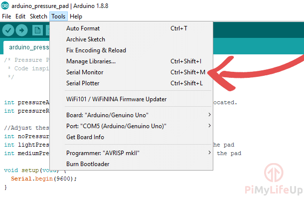
Now, load up the serial monitor by going to tools->serial monitor or ctrl+shift+M.
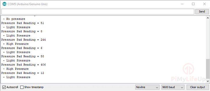
You should see your code in action with an output like below. If you’re seeing gibberish, then make sure your baud rate is set correctly.
Uses in Projects
There are plenty of uses of a force sensing resistor in Arduino projects. Below is just a few examples of what you can do.
- You can connect multiple force sensing resistors to the Arduino and have them act as inputs. For example, you can use them to play a tune each time to tap the sensor.
- Have it act as a button for switching devices on or off.
- Use the sensor to brighten or dim lights when more or less pressure is applied to it.
I really hope that this Arduino force sensing resistor tutorial has guided you through everything you need to know. If you run into issues or found a problem, then be sure to leave a comment below.