In this tutorial, we’re going to make our very own Arduino dice circuit. This is a simple project and is great for introducing yourself to more of the basics of the Arduino.
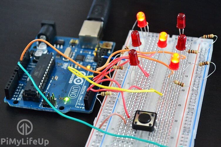
Much like the Arduino traffic lights project this project uses a variety of LEDS and resistors to make up the circuit. We will also be using a physical switch to tell the Arduino when to generate a new dice face.
You can go further with this project by making a special case for the circuit and LEDs. Excellent if you want some electronic dice to play your next board game with.
If you want to see how to do this project visually then be sure to check out the video below. We go through all the steps you need to know to get this up and running.
Equipment
The equipment you will need in this Arduino dice project is listed below.
Recommended
- Arduino Uno Amazon
- 7x LEDs Amazon
- 7x 100 ohm Resistor Amazon (Brown, Black, Brown)
- 100k ohm Resistor Amazon (Brown, Black, Yellow)
- Physical switch Amazon
- Breadboard Amazon
- Breadboard wire Amazon
Video
I have gone and prepared a video that will take you through all the steps to set up this dice circuit and bring it to life using the Arduino.
If you prefer a detailed written tutorial, then you can find it right underneath the video.
Building the Arduino Dice Circuit
The dice circuit is a relatively easy one and can be quickly assembled. There are ways to improve the circuit, but for this tutorial, we will keep it basic.
I have made a circuit diagram below to help you be able to place everything in the right place. I will explain more about the circuit straight underneath the diagram.
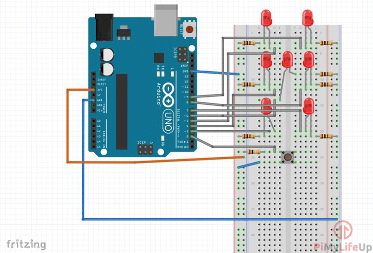
A switch is set up in a H like circuit, for example in our diagram it is a sideways H. Upper left and upper right leads are separate from the bottom leads. When you press the button it connects the upper and bottom leads forming a circuit thus activating our dice.
We run a 3v3 connection to the switch and have a 100k resistor to ground. In between the 100k resistor and the switch we have the wire running to pin 2. This will detect whenever the switch has been pressed.
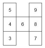
All of LEDS are positioned to resemble a die face. I have spaced these out a bit more so it’s easier to see on the diagram circuit above. You can place yours much closer together if you would like it to look much more like a proper die.
Each of LEDS are connected to the ground rail via a 100-ohm resistor. The positive end of the LEDS are then connected to a pin on the Arduino. You can see which LEDS are connected to which pin in the table below.
Making the Arduino Dice Circuit Come To Life
The code in this project is again very similar to the traffic light project. However in this one we introduce a input device (switch) and also produce a random number using the “randomSeed()” function.
This code is pretty long so I recommended downloading it from here or from our GitHub. I will take a few snippets from the code explain exactly what we’re doing to help you better understand the code.
In the example below, I am declaring the variables. “BottomLeft” refers to the location of the LED this makes it easier to identify when editing the script. The number we’re giving these variables are the pins that the LEDs are connected to.
The “state” and “randNumber” variables will be used for the storing of numbers. You will see this in action in a bit.
int button = 2;
//LED for DICE
int bottomLeft = 3;
int middleLeft = 4;
int upperLeft = 5;
int middle = 6;
int bottomRight = 7;
int middleRight = 8;
int upperRight = 9;
int state = 0;
long randNumber;Copy
This next code snippet is the setup and is where we assign pins to be either output or inputs and anything else we need to set up before we execute any further code. We use RandomSeed for setting up a random number generator.
//Initial setup
void setup(){
  pinMode(bottomLeft, OUTPUT);
  pinMode(middleLeft, OUTPUT);
  pinMode(upperLeft, OUTPUT);
  pinMode(middle, OUTPUT);
  pinMode(bottomRight, OUTPUT);
  pinMode(middleRight, OUTPUT);
  pinMode(upperRight, OUTPUT);

  pinMode(button, INPUT);
  Serial.begin(9600);
  randomSeed(analogRead(0));
}
Copy
The loop part of our script continues to loop through until the Arduino is either turned off or a new set of code is uploaded. At the start of Arduino dice loop we check to see if the switch has been pressed (high).
If the conditions are met, then we change the state to 1 and get a random number between 1 and 7. Once we have the random number we check to see what it is and run the relevant function.
Once the function is done we wait for 4 seconds and then turn the LEDS off and return to our normal state of 0.
void loop(){
  //Read our button if high then run dice
  if (digitalRead(button) == HIGH && state == 0){
    state = 1;
    randNumber = random(1, 7);
    delay(100);
    Serial.println(randNumber);

    if (randNumber == 6){
      six();
    }
    if (randNumber == 5){
      five();
    }
    if (randNumber == 4){
      four();
    }
    if (randNumber == 3){
      three();
    }
    if (randNumber == 2){
      two();
    }
    if (randNumber == 1){
      one();
    }
    delay(4000);
    clearAll();
    state = 0;
  }
}
Copy
Below is an example of the six function. This function is called whenever the dice produces the number six. As you can clearly see, it turns all the relevant LEDS to high.
This will make all the required LEDS that form six, turn on so you get the correct dice face displaying on the circuit.
void six()
{
  digitalWrite(bottomLeft, HIGH);
  digitalWrite(middleLeft, HIGH);
  digitalWrite(upperLeft, HIGH);
  digitalWrite(bottomRight, HIGH);
  digitalWrite(middleRight, HIGH);
  digitalWrite(upperRight, HIGH);
}Copy
Again, this page doesn’t have the entire code so don’t forget to download it so you can put it on your Arduino. You can download it from here, or find it on our GitHub.
I hope that you enjoy this Arduino dice project and that it has helped teach you more about the basics of the Arduino and coding. If you want to leave feedback, have questions or anything else be sure to leave us a comment below.


what does the button do
If pressed, it simulates a roll of the dice, then updates the LEDs with the new value.
Can you please do the code over again for the Arduino dice project its says “five was not declared in this scope.” it also say that for 1,2,3,4,5,6. Can you please help?
Hi Troy,
As mentioned in the tutorial, we stored the full code over at GitHub or as a download.