In this Raspberry Pi light sensor tutorial, I show you how to connect the photoresistor sensor up to the GPIO pins correctly.

Lastly, I show you how it can be used in a simple python script, so you’re able to gather and use the data from it.
This photoresistor is yet another sensor that I will be looking at incorporating into future projects such as a light-activated alarm clock.
I explain a bit further down each of the parts that I will be using in this circuit. Be sure to read up on it if you need more information on these.
It is important to note that for this tutorial, I am just using a simple photocell sensor. While these sensors are perfect for some tasks, they might not be as accurate as you would like.
If you want to see step by step on how to set up the light sensor circuit and code, then be sure to check out the video just under the equipment list.
Equipment
You will need the following equipment to be able to complete this Raspberry Pi light sensor tutorial.
You can do this without any breadboard gear, but I would highly recommend investing in some if you plan on doing a lot of circuitry work.
Recommended
- Raspberry Pi Amazon
- Power Supply Amazon
- Micro SD Card Amazon
- Ethernet Cable Amazon or Wi-Fi Amazon
- LDR Sensor Amazon (Light sensor)
- 1uF Capacitor Amazon
Optional
- Raspberry Pi Case Amazon
- USB Keyboard Amazon
- USB Mouse Amazon
- GPIO Breakout Kit Amazon
- Breadboard Amazon
- Breadboard Wire Amazon
Video
The video contains almost everything the text version of this tutorial does. It’s perfect if you prefer to see things done. You will also get to see how the circuit should perform once you are done.
You can find text instructions and information right underneath the video.
The Raspberry Pi Light Sensor Circuit
The circuit we are going to make for this tutorial is super simple and is great for anyone who is just starting out with circuitry.
Light Dependent Resistor (LDR)
The light-dependent resistor or also known as the LDR sensor is the most important piece of equipment in our circuit. Without it, we wouldn’t be able to detect whether it is dark or light.
In the light, this sensor will have a resistance of only a few hundred ohms while in the dark, it can have a resistance of several megohms.
Capacitor
The capacitor in our circuit is included, so we’re able to measure the resistance of the LDR sensor.
A capacitor essentially acts like a battery, charging up while receiving power and then discharging when no longer receiving power. Using this in series with the LDR, we can work out how much resistance the LDR is giving out, thus being able to tell whether it is light or dark.
Circuit Assembly
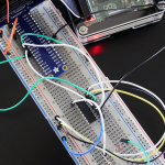
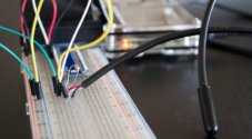
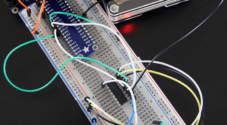
To get the light sensor circuit built correctly, follow the steps below. Alternatively, check out the circuit diagram right underneath the steps.
In the following steps, I am referring to the physical numbers of the pins (Logical order).
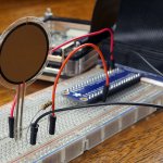
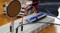
1. First, connect pin #1 (3v3) to the positive rail on the breadboard.
2. Next, connect pin #6 (ground) to the ground rail on the breadboard.
3. Now place the LDR sensor onto the board and have a wire go from one end to the positive rail.
4. On the other side of the LDR sensor, place a wire leading back to the Raspberry Pi. Hook this to pin #7.
5. Finally, place the capacitor from the wire to the negative rail on the breadboard. Make sure you have the negative pin of the capacitor in the negative rail.
We’re now ready to move onto the Python code. If you have any trouble with the circuit, refer to the diagram below.

The Light Sensor Code
The code for this project is pretty simple and will tell us roughly whether it is light, shady, or completely dark.
If you’re new to Python, I recommend taking a quick crash course on the basics of Python.
The biggest problem we face with this circuit is the fact that the Pi doesn’t have any analogue pins. They’re all digital, so we can’t accurately measure the variance in resistance on our input.
This lack of analogue pins wasn’t a problem in the motion sensor tutorial since the output from it was either high or low (Digital). Instead, we will measure the time it takes for the capacitor to charge and send the pin high. This method is an easy but inaccurate way of telling whether it is light or dark.
I will briefly explain the Raspberry Pi light sensor code and what it does. If you want the code, you can copy and paste it or download it from my GitHub.
To begin, we import the GPIO package that we will need so that we can communicate with the GPIO pins.
We also import the time package, so we’re able to put the script to sleep for when we need to.
#!/usr/local/bin/python

import RPi.GPIO as GPIO
import timeCopy
We then set the GPIO mode to GPIO.BOARD, and this means all the numbering we use in this script will refer to the physical numbering of the pins.
Since we only have one input/output pin, we only need to set one variable. Set this variable to the number of the pin you have acting as the input/output pin.
GPIO.setmode(GPIO.BOARD)

#define the pin that goes to the circuit
pin_to_circuit = 7Copy
Next, we have a function called rc_time that requires one parameter, which is the pin number to the circuit. In this function, we initialize a variable called count, and we will return this value once the pin goes to high.
We then set our pin to act as an output and then set it to low. Next, we have the script sleep for 10ms.
After this, we then set the pin to become an input, and then we enter a while loop. We stay in this loop until the pin goes to high, this is when the capacitor charges to about 3/4.
Once the pin goes high, we return the count value to the main function. You can use this value to turn on and off an LED, activate something else, or log the data and keep statistics on any variance in light.
def rc_time (pin_to_circuit):
    count = 0

    #Output on the pin for
    GPIO.setup(pin_to_circuit, GPIO.OUT)
    GPIO.output(pin_to_circuit, GPIO.LOW)
    time.sleep(0.1)

    #Change the pin back to input
    GPIO.setup(pin_to_circuit, GPIO.IN)

    #Count until the pin goes high
    while (GPIO.input(pin_to_circuit) == GPIO.LOW):
        count += 1

    return count

#Catch when script is interrupted, cleanup correctly
try:
    # Main loop
    while True:
        print(rc_time(pin_to_circuit))
except KeyboardInterrupt:
    pass
finally:
    GPIO.cleanup()Copy
Running the Code on your Raspberry Pi
This step is incredibly easy, but I will quickly go through the steps so you can have it up and running on your Pi as quickly and smoothly as possible.
Like all the tutorials on this website, I am using Raspbian. If you need help on getting it installed, then check out my guide to installing Raspbian.
While all the software packages should already be installed, in some cases, it may not be.
If you want to learn more about the GPIO pins and how to update and install the software, then be sure to check out my tutorial on setting up the GPIO pins on the Raspberry Pi.
You can download the code by using git clone. The following command will do exactly just that.
git clone https://github.com/pimylifeup/Light_Sensor/
cd ./Light_SensorCopy
Alternatively, you can copy and paste the code just make sure the file is a Python script. I like to use the nano text editor for creating and editing Python scripts.
sudo nano light_sensor.pyCopyOnce you are done in the file, simply use CTRL + X then Y to save and exit.
Finally, run the code by using the following command.
sudo python light_sensor.pyCopyI hope you now have the script working, and you’re receiving data that correctly reflects the changes in light on the sensor. If you’re having trouble, please don’t hesitate to leave a comment below.
Improving Accuracy & Possible Uses
There are countless uses for a light sensor in a circuit. I will just name a few that I thought of while I was writing up this tutorial.
Light Activated Alarm – I mentioned this one earlier, but you can use the LDR to detect when it starts to get light so you can sound an alarm to wake you up. If the program and sensor are accurate, then you can have the alarm slowly get louder as it gets lighter.
Garden monitor – A light sensor could be used in a garden to check how much sun a certain area of the garden is getting. This could be useful information if you’re planting something that needs lots of sun or vice versa.
Room Monitor – Want to make sure lights are always turned off in a certain room? You could use this to alert you whenever some light is detected where it shouldn’t be.
There is so much you can do with this cool little sensor, but also remember if you require something a little more accurate than the photocell, then look at something like the Adafruit high dynamic range digital light sensor.
I hope you have been able to set up this Raspberry Pi light sensor without any issues. If you do come across a problem, have feedback, I have missed something, or anything else you would like to say, then feel free to drop a comment below.
Credit: This tutorial is based on Adafruit’s Resistor Sensor tutorial.

Are there libraries that need downloading?
You will need the Raspberry Pi GPIO package installed.
Complete noob here and in the process of building my programmable crimbo light show. Now I am assuming this can be used in conjunction with a relay board and other jems like lightshow pi. So it gets to a certain ambient lighting level sensors powers the replays at which point light programs kicks voila magical chistmas light show.
This circuit works well . I can able to determine the time taken by the capacitor to charge and discharge. But i need to find the resistance across the photoresistor at every instance because i am trying to give a feedback loop. So how to find the resistance from the time. Kindly tell me the relation.
How to find the resistance from the time?
Because you know the time then you will be able to calculate the frequency and therefore use the standard formula.
The relationship is:
1/R = 2 Pi f C
Where
Pi is 3.142
f is the frequency in Hz
C is the capacitance in Farads
Failing that, substitute the photo resistor for a 10M variable resistor and make measurements with which to make your comparisons.
I believe that you are stretching your understanding at the moment and so that last option may be your best option.
Good luck with the feedback loop . . .
In very broad terms; how many shades of dark do you require? a test inside the while loop to ascertain that the count had exceeded a “dark” count value is probably sufficient, to trigger an early exit from the while loop.
This will tell you what you need to know; it’s DARK and return in a reasonable time period.
I am trying to use this sensor in node red. And I am not sure how to get input from the sensor. I tried using rpi-gpio node but it only gives 1/0 value not ldr value. What should I do?
I used GPIO 18 (which takes 0-1 values) and I used the LDR in a comparator circuit (digital). This circuit could be tweaked via a variable resistor (potentiometer) to my desired ambient light threshold level to turn the comparator output on or off.
If you want a numeric value instead, I believe you have to use the LDR in parallel to a capacitor of fixed value. Then the RPi will first charge the cap, then stop charging and time how long it takes the LDR to drain the cap below threshold. It repeats this charge/discharge process over and over continuously. For help with this method (analog), someone else will have to assist.
Okay, so my statement about the R/C in parallel is wrong (I just looked at the diagram above). I will defer to those who have used the R/C (LDR/CAP) method and back out now. 🙂
Excellent tutorial. So simple and it just works. I’ve used it in a simple CCTV setup using a raspberry pi camera that takes pictures every 2 seconds after someone has switched on the lights in my office. Caught the guy on the first day.
I want to use an LDR or photo-transistor for a dimmer on my clock project, which uses an Adafruit 1.2″ LED display and a Raspberry Pi Zero.
Instead of using the RC circuit with an RC timing routine in the Python code, I’m thinking about using a comparitor circuit instead. I figure I can choose a resistor value for the detector side of the comparitor that will set the threshold properly. Alternatively I could use a potentiometer as the resistor for the detector side so the threshold can be adjusted.
Additionally, I already have added the code to the code which will dim the display if GPIO pin 18 is pulled low. I only need to output a Hi/Lo signal based on the detector compared to a reference voltage (vcc/2) using a resistor based voltage divider (VCC to 10K+10K to GND).
I successfully got the LDR (Cadmium Sulfide photocell) circuit working using the LM339 comparator. The negative input connects between two 10K resistors (between 3.3v and GND). From the positive input a 56K resistor connects to 3.3v and the photocell connects to GND.
I put in a female header for the resistor so it can be changed for different values as necessary. I started with 4K7 but it didn’t switch to bright at a low enough light level. I tried a 15K with better results, and then tried the 56K. Subdued ambient lighting keeps the display bright but turning off the lights causes the display to dim.
Hi
Can I substitute capacitor of some other capacitance here(say 100uF)
I did this and when the sensor is in a pitch black room, it takes forever to respond. I’m trying to use this in a project where the monitor turns on/off based on if the room is dark, and when the room is pitch black, it basically just sits and if it does ever come back, the number is insanely high. Into the hundreds of millions. However as soon as I turn the light on, the numbers start flowing in. I tried a few other scripts and I still can’t get it to perform the way I want. Is there anyway to change the amount of time it takes for it to return a value?
BTW I figured this out. What I did was set a timeout Bash script that ran the python script. if it took longer than 2 seconds to return a variable, it turned the monitor off and exited the script. If it didn’t take 2 seconds, it turned it on. It works well!
Any chance you could share the script? I’ve been looking everywhere but can’t find the right script for the solution.
The_stig I found an easy solution to your problem. The reason “while loop” takes so much time to complete a cycle in a pitch black room is because the LDR is not letting electricity pass to the electrolytic capacitor.
In other words, The more light hits the LDR the more electricity passes through the circuit and charges the capacitor faster.
As light decreases to complete dark, the “while loop” slows down to almost to the point of desperation because the capacitor is not being charged as fast.
To solve this problem, Do the following:
change the python while loop script from:
Secondly, you need a dimmed light barely illuminating the LDR. Because we have a threshold of 100000 anything above this number “It’s Dark”. Anything below “It’s Sunny”.
The LED will provide just enough light to keep the While Loop running smoothly in a very dark room, and without spoiling the code.
Now, for the hardware you need:
To place a small Red LED about 2 cm from the LDR. Connect the negative side of the LED to a 2k ohm resistors ( or two 1k ohm resistor in series). Finally, connect the positive end of the LED to positive and YOU ARE DONE!
Troubleshoot:
if is dark and you get a “It’s Sunny”, your LDR is receiving too much light from the LED.
To compensate, either use a bigger resistor (i.e 3k ohm), increase the number in the python code from 100000 to 150000, or increase the separation of your LED from the LDR.
Good Luck!