The Arduino battery tester is a pretty cool nifty tool that you can use to check how charged a battery is.

This is perfect for anyone who wants to know roughly how long a battery has left before it runs out of charge.
This battery tester is a pretty barebones beginner Arduino project but it can be extended to be a proper setup with proper casing and more. I go into detail at the end of the tutorial on how you could extend this project one step further.
A project like this one really showcases how you can make such a handy setup using the Arduino and a few pieces of equipment. It is also a great project for learning more about the basics of coding and electronics.
This battery tester isn’t super accurate and is probably best as a learning tool more than a precise measurement tool. I still highly recommend building this project as it is both fun and educational.
Equipment
The equipment that I use in this Arduino battery tester project is right below. If you already have a starter kit, then you should have most of the equipment already, except for the Zener diode.
Recommended
- Arduino Uno Amazon
- Green LED Amazon
- Yellow LED Amazon
- Red LED Amazon
- 5.1k Zener Diode Amazon
- 100 ohm resistor Amazon
- 2.2k ohm resistor Amazon
- Breadboard Amazon
- Breadboard Wire Amazon
Optional
Video
If you want to see how to make this project, then be sure to check out my video below. I go through all the steps required to getting this cool battery tester project up and running.
You can find the full written tutorial on building this basic battery tester right underneath the video.
Assembling the Arduino Battery Tester Circuit
This battery tester circuit is pretty easy to assemble. If you have been following my Arduino tutorials, then you will notice we’re using a new component called the Zener diode.
The Zener diode will allow you to test batteries that have a voltage greater than 8 volts. A Zener diode works by allowing current to flow in one direction until it hits the breakdown voltage (limit on the diode, in our case it is 5.1 volts). Once it hits this limit, it allows the voltage to go in the reverse direction. This can help protect parts that can only handle a certain amount of voltage. In our case the Arduino.
The 2.2k ohm resistor reduces the current coming from the battery to something that the Arduino will be able to take in. If your current is too high, then it may damage your Arduino.
The circuit also has three different LEDs, each of these LEDs represents roughly how much charge there is left in the battery.
- Red will represent the battery is low/almost dead.
- Yellow will represent the battery being roughly half used up.
- Finally, the green will represent the battery being full.
For each of the LEDs, we connect a 100-ohm resistor from the ground pin to the ground connection, so we don’t burn out the LEDs. This is very similar to what we did in the Arduino traffic light tutorial.
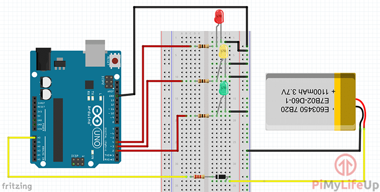
I will now quickly go through the steps of putting this circuit together. Underneath the instructions you will find a circuit diagram if you find it easier just following that.
1. Wire the ground pin on the Arduino to the ground rail on the breadboard.
2. On the breadboard place the green, red and yellow LEDs. Connect the ground pins to the ground rail.
3. Place a 100-ohm resistor onto positive end of the LEDS then hook a wire from a resistor to the relevant pins on the Arduino.
The following LEDs should connect to the relevant pin numbers.
- Red LED = 4
- Yellow LED = 3
- Green LED = 2
4. Now connect from analogue pin 0 (A0) to the breadboard. After this add a 2.2k resistor and the Zener diode (with the line on Zener diode facing towards the Arduino). Finally have a loose wire coming from the other end of the diode.
5. Finally, have a loose wire connected to the ground rail.
The code
The code for this Arduino battery capacity tester project is straightforward, but I will explain each bit, so you’re able to understand what we’re doing. If you just want the code and no explanations, then you can download it here or on our GitHub.
Firstly, we need to set up all our variables. This includes making sure the LED variables are all assigned to their relevant pin number mentioned earlier.
The analogValue variable is where we will be storing the value that comes from the analog input. We then do a calculation (Which I will explain later) and store the resulting number into a variable called voltage.
Finally, ledDelay is how long you want the LEDs to remain on before switching off.
int greenLed = 2;
int yellowLed = 3;
int redLed = 4;

int analogValue = 0;
float voltage = 0;
int ledDelay = 1000;Copy
The setup function is called once and the perfect place to set up all our pins. In this particular program, we only need to set up all our LED pins as outputs.
void setup()
{
  pinMode(greenLed, OUTPUT);
  pinMode(yellowLed,OUTPUT);
  pinMode(redLed,OUTPUT);
}Copy
Inside the loop function, we will do a couple of things. Firstly, we read the analog pin, the value from this pin will be between 0-1023. We will need to do a calculation to convert this to a variable, so we simply multiply the analogValue by 0.0048 to do this.
void loop()
{
  analogValue = analogRead(A0);
  voltage = 0.0048*analogValue;Copy
This last part we compare our calculated voltage and compare this to our defined voltage values. Whenever the voltage falls between a set of values, we merely turn the relevant LED. You can change the voltage variables to get the LEDs to display how you like.
  if( voltage >= 1.6 )
    digitalWrite(greenLed, HIGH);
  else if (voltage > 1.2 && voltage < 1.6)
    digitalWrite(yellowLed, HIGH);
  else if( voltage <= 1.2)
    digitalWrite(redLed, HIGH);

  delay(ledDelay);
  digitalWrite(redLed, LOW);
  digitalWrite(yellowLed, LOW);
  digitalWrite(greenLed, LOW);
}Copy
Once you are done with the circuit simply plug the Arduino into a computer and upload the code. Once this is done, we can continue onto testing and checking that it is working correctly.
Testing it all
When you first turn on and deploy the new code to the Arduino, you will notice that it keeps jumping between the LEDs. This is because the analog input wire is floating and picking up noise causing our program to detect false positives.
To stop the jumping, you can simply ground the analog wire to the ground rail when not in use. You can also try grounding the other analog pins to help reduce the amount of noise it’s picking up.
To test it, all you need to do is hook up a battery to the two wires. Place the ground wire to the negative end of the battery and the positive wire to the positive end of the battery.
The Arduino should pick up the voltage and tell the relevant LED to light up. If it doesn’t then have a look at adding some debug lines for the battery input. This should tell you if there is something wrong with reading the input or there is simply a mistake for displaying the LEDs.
Extensions
Now, this tutorial just covers the very basics of setting up a battery tester using the Arduino. You can extend it to be a lot better and be more of a permanent device that you can use everyday.
One improvement is to print the output to an LCD screen connected to the Arduino rather than using LEDs. This can give you more accurate information since we can write values to a screen.
You could also add a proper battery holder instead of using the two wires to check the life of the battery. This will probably make it a bit safer and make it look more like a professional battery tester unit.
A nice solid case would work well with a battery holder. Having the ability to 3D print one would be perfect for achieving this. Having a battery pack for the Arduino, so that it can be portable will make it perfect for anyone who needs test batteries but isn’t near a power source.
I hope that you have been able to build this basic but cool Arduino battery tester. If you have come across any issues or have anything else that you would like to share, then feel free to leave a comment below.


Thanks for posting this great simplified easy-to-pick example!!
This is a nice and simple project for beginners since it teaches a lot about the Arduino and coding. The Zener diode was a nice touch. There is the issue that it is not a “real” battery tester where the battery is tested “under load” with a constant set current. I understand your choice of voltages from my own checking and online info.
From one source, a dead battery with no load measures 1.4V but under a load of e.g. 100 ohms it gives 1.0 Volts. A good AA battery with a 100 ohm load gives roughly 1.4 volts. I have several real battery testers as well as schematics. Your measuring system is really a Voltmeter that is suitable for measuring voltages but not battery capacity. This should be pointed out.
It is a good starter project as stated clearly. If anyone is interested, looking up the old RadioShack 22-091 battery tester provides 2 tables. One shows the constant current for each rotary switch battery type while the other shows the switches/settings. It compares well with new testers. It also tests Ni-Cd, Ni-MH and Lithium batteries. cheers.