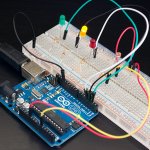
In this tutorial, we will be building a simple Arduino motion sensor that makes use of a PIR sensor to be able to detect motion.
This simple circuit can be extended to do some pretty cool stuff, for example, activate lights, a speaker and much more.
In this particular tutorial, we will be making use of both a LED and piezo buzzer to alert us when motion has been detected through the PIR motion sensor.
You’re able to adapt and change this project to have a Python script do other things when motion is detected. Such as trigger a camera to take a photo and much more.
This project is pretty simple but is an excellent example of how you can easily integrate sensors with the Arduino. It’s super easy to build on this tutorial and make some pretty cool Arduino setups.
Equipment
The equipment that you will need for this project is listed below. You won’t need all the parts, but I recommend that you at least have one piece that can show you when motion is detected, for example, the buzzer or LED.
Recommended
- Arduino Uno Amazon
- Red LED Amazon
- 2x 100 ohm Resistor Amazon (Brown, Black, Brown)
- Piezo Buzzer Amazon
- PIR Sensor Amazon
- Breadboard Amazon
- Breadboard wire Amazon
Video
If you want to see how to put together the PIR Motion sensor Arduino circuit, then check out the video below. I also go through the code and give a brief explanation on what it does.
Alternatively, if you prefer to read, then right beneath the video are some detailed instructions on how to assemble this cool Arduino project.
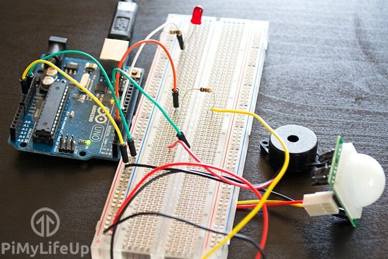
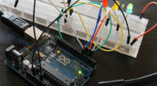
Assembling the PIR Motion Sensor Arduino Circuit
Our circuit is like most of the projects we have built to date, simple. You won’t require a massive amount of parts to get this working.
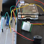
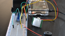
The PIR sensor is probably the most complicated part we have in our circuit. On the PIR sensor, you can adjust the sensitivity and time for the detection of motion. This device has 3 wires coming from it.
- The red wire is for a positive power source (5v).
- The black wire is for ground.
- Finally, our yellow wire is the output and turns high whenever motion is detected.
You will find that a piezo buzzer is a super simple speaker. It has a ground wire and a positive wire. We will connect the positive wire to a pin on the Arduino. Whenever the pin goes to high, the speaker will make a sound.
The rest of our equipment for this motion sensor circuit is pretty straightforward and is listed above.
Below is the PIR motion sensor Arduino circuit diagram and underneath it, I go into step by step on how to put this device together.
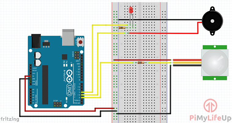
1. First, run a wire from the 5V pin to the positive rail on the breadboard.
2. Now run a wire from the ground pin to the ground rail on the breadboard.
3. For the PIR sensor do the following steps:
- Run the black wire to the ground rail.
- Run the red wire to the 5v rail.
- Place a 100-ohm resistor onto the breadboard.
- Run the yellow wire to one end of the resistor and then another wire from the other end of the resistor to pin 2.
4. Now for the Piezo buzzer do the following:
- Run the red wire to pin 3 on the Arduino.
- Now the black wire to the ground rail on the breadboard.
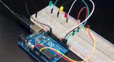
5. Now for the red LED do the following:
- Run a 100-ohm resistor from the ground rail to a spot on the breadboard.
- Connect the negative end of the LED to the resistor and the other positive end to another spot on the breadboard.
- Run a wire from pin 4 to the positive pin on the red LED.
Before we move on you may want to double check your connections to make sure they’re all done properly. The circuit diagram above is probably the best thing to refer to.
Arduino Motion Sensor Code
Again, much like most of our beginner projects the code for the Arduino motion sensor will be very simple. This is great if you’re just starting out and wanting to learn more about the Arduino coding language.
If you just want to download the PIR motion sensor code, then you can find it here or over on our GitHub. Once downloaded just open in the Arduino application and upload to your Arduino when you have the circuit complete.
In this first block of code, we set four different variables. The first 3 are setting pin numbers to a variable. This is so we can easily reference and recognize that pin further down in the code.
The fourth variable (motionDetected) is where we store the state of our PIR sensor. Low means that no motion has been detected while high means it has been detected. At the start of our script, we will keep this variable as low.
int ledPin = 4;                // Pin LED is connected to
int piezoBuzzerPin = 3;     // Pin Piezo Buzzer is connected to
int pirSensorPin = 2;               // PIN PIR Sensor is connected to

int motionDetected = LOW;             // Start MotionDetected as low (No motion detected)Copy
In this next block of code, we set up all our pins and anything else we may need to initialize.
For both the piezo buzzer and the LED we set these to act as outputs as we want to turn these on and off.
Now, for the PIR sensor, we want to listen to it for when motion is detected so we will set it to act as an input.
Next, we set the Serial.begin(9600), so we are able to debug our code if required. The 9600 is the baud rate, change this if you have different settings on your computer. Serial.println("hello") will allow you to print debug messages to the console.
Finally, we have a delay for 5 seconds to allow for the PIR sensor to initialize. You can tinker with this value for the shortest delay without the sensor throwing false positives.
void setup() {
  pinMode(ledPin, OUTPUT);      // declare LED as output
  pinMode(pirSensorPin, INPUT);     // declare the PIR sensor as input
  pinMode(piezoBuzzerPin, OUTPUT); //declare buzzer as output
  Serial.begin(9600); //Set serial out if we want debugging
  delay(5000); //Allow time for the PIR Sensor to calibrate
}Copy
Now we have the core of our program. The loop function will continue to loop through until power is disconnected from the Arduino or a new program is uploaded.
Firstly, we check to see if the PIR sensor is high or not. If it is high, we enter the if statement, otherwise, we keep the LED and the piezo buzzer off.
If the sensor is high, we turn the LED on and set the buzzer to be at a certain pitch by using analog output. We then wait for 100 Ms then turn the LED off and change the pitch of the Piezo buzzer. We repeat this until the PIR sensor goes back to low (No motion detected).
void loop(){
  motionDetected = digitalRead(pirSensorPin);  // Read the PIR sensor
  if(motionDetected == HIGH) //If motion detected
  {
    digitalWrite(ledPin, HIGH);
    analogWrite(piezoBuzzerPin, 200);
    delay(100);
    analogWrite(ledPin, LOW);
    analogWrite(piezoBuzzerPin, 25);
    delay(100);
  }
  digitalWrite(ledPin, LOW);
  digitalWrite(piezoBuzzerPin,LOW);
}Copy
Once you have the code within the Arduino program simply upload to the Arduino and your circuit should come to life. If it doesn’t, recheck all your connections and make sure the correct wires are hooked up to the correct pins on the Arduino.
If you’re curious about doing a similar project, but for the Raspberry Pi, then you should certainly take a look at my PIR sensor tutorial.
I hope you have been able to build a fully working Arduino motion sensor from this tutorial. If you come across any problems, I have missed something or anything else then feel free to leave us a comment below.

Hi Emmet, there is a very easy hack to power this particular sensor from 3.3v instead of 5v, might be useful when powering by 2xAA batteries, esp32 projects in particular
how can i change time of response of PIR sensor
Hi Kareem,
This will depend on the PIR sensor that you are using. Some have potentiometers on them that you can tweak to control the delay and sensitivity of the sensor.
Code wise we are looping continually without any delays so there is nothing on that front that you can do to improve the response time.
Cheers,
Emmet