In this Arduino light sensor tutorial, I will go through the basics of setting up a photoresistor, so you’re able to detect changes in light easily.
This little device can be extremely handy in a lot of projects where measuring the amount of light is important.
This tutorial is incredibly simple but will hopefully explain and show how you can use a photoresistor in your next project. You won’t need very much equipment with most of it being very basic parts that you would probably already have if you bought an electronics starter kit.
This is very similar to the Raspberry Pi LDR sensor tutorial, but our circuit & code is a lot easier. This is because the Arduino has analog pins making it super easy to read the value from something such as an analog sensor.
Equipment
The equipment that you will need for this Arduino light sensor tutorial is pretty basic as I mentioned earlier.
The LED’s that I am using is just for some visual feedback, so these aren’t essential if you’re willing to read output variables in the command line.
Recommended
- Arduino Uno Amazon
- Photo Resistor Amazon
- 220 ohm Resistor Amazon
- Breadboard Amazon
- Breadboard wire Amazon
Optional
Video
If you want to see me go through this tutorial step by step, then be sure to check out my video below.
The video is an excellent way to learn as you can see how the tutorial progresses and how things work.
You can check out the full written tutorial right under the video.
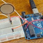
The Arduino Light Sensor Circuit
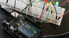
The circuit we need to build is pretty basic, and you shouldn’t have too much trouble setting it up. I will briefly mention each of the parts that are in it and how to put it all together.
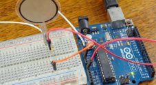
The light sensor or also known as a photoresistor is the piece of equipment that we will be using to tell how light or dark it is. When it is dark the resistor will have a very high resistance of up to 10 megohms. When it is light, it will have only a few hundred ohms of resistance.
You can often find out roughly the resistance by looking at the device datasheet. It is likely to refer to lux the unit of illuminance and provide you with information on the approximate resistance at a certain lux amount.
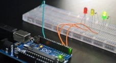
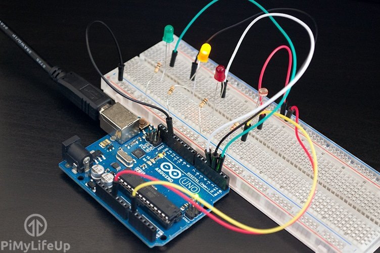
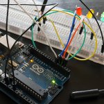
The LEDs in our circuit will represent the current amount of resistance across the photoresistor.
- Green will be when it is at low resistance (Lots of light).
- Yellow will be when there is medium resistance across the LDR (Shady).
- Finally, red will represent for when it’s at high resistance (Very Dark).
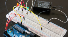
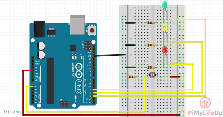
1. First hook the 5V wire up from the Arduino to the positive rail on the breadboard.
2. Next, hook the ground pin to the ground rail.
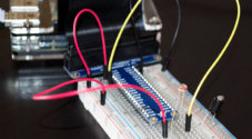
3. Now, place the photoresistor onto the breadboard.
- Hook a wire from one end to the positive rail.
- On the other end have a wire go back to A0 (analog).
- Finally, on the other side of the wire add a 220-ohm resistor that goes to the ground rail.
4. Place the 3 LEDs onto the breadboard. (Green, Yellow, Red)
- On each of the LEDs add a 100-ohm resistor and have this go to the ground rail.
- Now place a wire back to the Arduino for each of the LEDs. Red to pin 4, yellow to pin 3, and finally green to pin 2.
5. Now we’re ready to turn it on and deploy the code. If you have had any trouble, please refer to the diagram below.
The Code
Much like the circuit, the code for this Arduino photoresistor tutorial is very easy to follow. Again this is just covering the basics of this cool electronics part if you want to see some possible implementations, then check out some ideas I have at the bottom of this guide.
If you want to download the code, you can find it for download at our light sensor Git repository.
Before we start doing anything we first need to set up all our variables. For this program, we will need 4 variables to store our pin numbers and 1 variable to store the value of the analog pin in. These are all of the type integers.
int greenLedPin = 2;
int yellowLedPin = 3;
int redLedPin = 4;

int lightSensorPin = A0;
int analogValue = 0;
Copy
Set all the pins for the LEDs to act as outputs. You don’t need to worry about setting up the analog pin.
void setup() {
  pinMode(greenLedPin, OUTPUT);
  pinMode(yellowLedPin,OUTPUT);
  pinMode(redLedPin,OUTPUT);
}Copy
The loop is pretty simple and shouldn’t be too hard to understand what’s going on. We first get the value from the analog pin, this is the photoresistor.
Once we have the value, we compare and turn on the relevant LED. For example, the red LED will be on when it’s dark, yellow for shady and finally green for light. After this, we delay for 200ms and turn all the LEDs to low and check again.
void loop(){
  analogValue = analogRead(lightSensorPin);
  if(analogValue < 50){
    digitalWrite(redLedPin, HIGH);
  }
  else if(analogValue >= 50 && analogValue <= 100){
    digitalWrite(yellowLedPin, HIGH);
  }
  else{
    digitalWrite(greenLedPin, HIGH);
  }
  delay(200);
  digitalWrite(greenLedPin, LOW);
  digitalWrite(yellowLedPin, LOW);
  digitalWrite(redLedPin, LOW);
}Copy
Once you’re done simply upload it to the Arduino and your circuit should come to life. You may need to tinker with the values inside the if statements as this can vary depending on your lighting conditions.
Troubleshooting
Now if you’re finding things aren’t working exactly as you would like, then it will be a good time to enter some debugging lines. If you don’t know how to setup debugging, then be sure to check out my tutorial on the Arduino serial monitor.
My advice would be set up a debug line telling you the value of the LDR input. This can vary so you might need to change the values in the code to something that works better in your conditions (outside, inside, etc).
A common problem is the light emitting from the red LED causes the light sensor to think that there is light. My best advice for this would be to move the light sensor away from the red LED as much as possible.
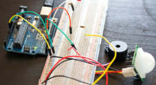
Possible Implementations
There are so many Arduino projects that you can implement a photoresistor into. I will quickly just mention a few that I thought of while I was writing up this tutorial.
- You could use the photoresistor in a light-activated alarm that alerts you if a room goes dark or light. Alternatively, you can use the same setup as a bedside alarm clock that gets louder as it gets brighter.
- You can use an LDR to activate lights when it starts to get dark. For example, this would work well if you have outside lights that light up some stairs or similar but only want them to be on when it gets to a certain level of darkness.
- You could also hook it up to a chicken hatch so that it automatically opens in the morning when it starts to get bright.
These are just a few ideas to what you could do. I will be looking at doing some cool Arduino beginner projects and possibly more advanced projects that utilize a lot of the sensors I have recently been talking about.
Conclusion
If you want to stay up to date on all the projects, tutorials and much more then be sure to either subscribe to our mailing list or follow us on any of the major social networks.
I hope you have been able to follow this Arduino light sensor tutorial without any issue. If you do come across any trouble, have feedback or anything else then please feel free to leave a comment below.